Doğru Kalınlığı Seçmek İçin Teknik Kılavuz 1100 Alüminyum Alaşımlı Çevreler: Malzeme Biliminden Mühendislik Uygulamalarına
1100 alüminyum alaşımı, ticari olarak saf alüminyumun tipik bir temsilcisi, dairesel boşluğunda (daire) biçim, pişirme kapları için temel bir hammadde görevi görür, aydınlatma armatürleri, elektrik bileşenleri, dekoratif öğeler, ve çeşitli damgalı parçalar. Kalınlık, as the most critical dimensional parameter of the sheet, makes its selection a multi-objective optimization problem that profoundly impacts the product’s functional performance, manufacturability, reliability, and total lifecycle cost. This article aims to establish a systematic technical framework for thickness selection. It delves into the coupling relationships between mechanical properties, şekillendirme süreçleri, termal davranış, economics, and standardization systems. Through quantitative analysis, case references, and a decision-making workflow, it provides high-level, practical professional guidance for engineering design, satın alma, and manufacturing personnel to achieve optimal utilization of the material’s properties.
 alüminyum levha daire
1. Material Property Review: The Nature of 1100 Alüminyum Alaşım
1100 aluminum alloy belongs to the 1xxx series of non-heat-treatable aluminum alloys, with the following primary characteristics:
- Kimyasal Bileşim: Alüminyum içeriği not less than 99.0%, with iron (Fe) and silicon (Ve) as main impurities. Iron and silicon exist as intermetallic compounds (E.G., FeAl₃), slightly increasing strength but marginally reducing ductility.
- Core Properties:
- Low Strength, Excellent Plasticity: Annealed (Ah öfke) yield strength is approximately 35 MPa, tensile strength about 90 MPa, with elongation exceeding 35%. This is the physical basis for its superior deep-drawing formability.
- Mükemmel Korozyon Direnci: The dense oxide film naturally formed on the surface ensures stability in most atmospheric and mild acid/alkali environments.
- High Thermal and Electrical Conductivity: Electrical conductivity is about 59% of the International Annealed Copper Standard (IACS), with thermal conductivity around 222 W/(m·K).
- Good Workability: Easily cut, stamped, bent, spun, ve cilalı.
- Non-Heat-Treatable: Its strength improvement is primarily achieved through cold working (gerinim sertleşmesi).
- Ortak Öfkeler: H14 (1/4 zor), H18 (tam sert) and other H-temper materials offer higher strength but reduced ductility. Thickness selection is typically based on the most commonly used Annealed (Ö) öfke, with subsequent strain hardening applied as needed.
2. The Five Core Dimensions of Thickness Selection and Their Quantitative Analysis
2.1 Dimension One: Functional and Performance Requirements
The end-use of the product is the primary driver for thickness selection. The table below systematically analyzes the directional requirements for thickness based on different functional needs.
Masa 1: Core Performance Requirements and Thickness Selection Guidance Based on Product Function
| Product Category |
Typical Examples |
Core Performance Requirements |
Primary Impact on Thickness |
Recommended Thickness Range (mm) |
Selection Logic Analysis |
| Derin Çekme / Stamping Parts |
Tencere gövdeleri, can bodies, lampshade housings |
Limit drawability, resistance to thinning and fracture, surface smoothness (no wrinkling) |
Thickness↓, material flow resistance↓, limiting drawing ratio (LDR)↑; but excessive thinness容易 leads to instability/wrinkling. |
0.5 – 2.5 |
Prioritize meeting the Çizim Oranının Sınırlandırılması. Select the thinnest possible thickness that can be formed while avoiding wrinkles. Requires consideration of drawing ratio calculations. |
| Light Load Structural Parts |
Equipment covers, parantez, protective shrouds |
Bending stiffness, vibration resistance, boyutsal kararlılık |
Stiffness ∝ t³. Thickness is the most effective means to increase stiffness. |
1.0 – 6.0 |
Design for stiffness using maximum allowable deflection as a constraint, back-calculate the minimum theoretical thickness, and apply a safety factor. |
| Load-Bearing / Connecting Parts |
Gaskets, simple support bases |
Verim gücü, shear resistance, crush resistance |
Load-bearing capacity is directly related to cross-sectional area (proportional to t). |
2.0 – 10.0+ |
Calculate working stress (bükme, compressive), ensure it is below the material’s allowable stress, and determine thickness accordingly. |
| Thermal Conduction / Heat Storage Parts |
Cookware bottoms, heat spreader bases |
Heat capacity, heat flux density, sıcaklık bütünlüğü |
Thickness↑, heat capacity↑, thermal inertia↑, temperature uniformity↑, but transient response slows. |
2.0 – 8.0 |
Denge transient heat transfer ve steady-state temperature distribution. Perform simplified 1D heat conduction calculations to evaluate temperature field. |
| Decorative / Appearance Parts |
İsim plakaları, panels, trim strips |
Düzlük, resistance to finger pressure deformation, surface finish quality |
Thickness must be sufficient to resist minor deformation during packaging, transport, and installation, ensuring appearance. |
0.3 – 1.5 |
Based on experience and analogy, meet basic “stiffness” gereksinimler. Excessive thickness is uneconomical and adds weight. |
| EMI Koruma / Sealing Parts |
Shielding covers, sealing gaskets |
Electromagnetic wave attenuation, sealing force from springback |
For low-frequency shielding, thickness must be greater than skin depth; for sealing, sufficient springback must be ensured. |
0.2 – 1.0 |
Calculate required thickness based on shielding effectiveness (dB) gereksinimler; or select based on compression set requirements. |
Key Technical Points: Quantitative Design for Stiffness and Strength
- Bending Stiffness Formula: For simply supported or cantilever beam models, the maximum deflection δ_max is related to thickness t as:
- Bending Stress Formula: Maximum bending stress σ_max = (M * y) / BEN, where M is the bending moment, y is the distance from the neutral axis to the surface (= t/2), and I is the area moment of inertia (for a unit width plate, I = t³/12). Böylece, σ_max ∝ 1/t². Increasing thickness significantly reduces working stress.
 Çok sayıda alüminyum disk
2.2 Dimension Two: Manufacturing Process Compatibility
The manufacturing process is the bridge transforming material into product, and its physical limits directly define the feasible range for thickness.
Masa 2: Constraints and Requirements of Key Manufacturing Processes on 1100 Aluminum Circle Thickness
| Process Type |
Process Description |
Core Process Parameters Affected by Thickness |
Feasible Thickness Range (mm) |
Process Limitations & Seçim Tavsiyesi |
| Derin Çekme |
Forming a flat blank into a hollow, open part |
Çizim Oranı (m=d/D), Punch-Die Clearance (z) |
0.3 – 3.0 (typical) |
Clearance z ≈ (1.1~1.2)T. Excessive thickness (t↑) requires enormous blankholder and drawing forces, increasing risk of fracture. Multi-stage draws may require intermediate annealing. Initial drawing ratio recommended ≥0.55. |
| Eğirme |
Forming by roller pressure on a rotating blank |
Spindle Speed, Feed Rate, Pass Reduction Rate |
1.5 – 20.0+ |
Thick plates (T>6mm) require power spinning, demanding higher equipment capability. Thickness must ensure part rigidity to avoid chatter. Preferred process for large, medium-thickness axisymmetric parts. |
| Bükme / Hemming |
Plastic bending along a straight line |
Minimum Inside Bend Radius (R_min) |
0.5 – 12.0 |
R_min depends on material ductility and bend direction relative to rolling. Rule of thumb: for 90° bend, R_min ≈ (0.5~2) * T. Larger t requires larger R_min. Bend direction should be perpendicular to rolling direction for smaller R_min. |
| Körleme / Yumruklama |
Separation process to obtain outline |
Die Clearance, Cut Edge Quality, Tool Life |
0.2 – 6.0 |
Clearance is typically 8-12% malzeme kalınlığı. t too small leads to high burr ratio; t too large requires larger press tonnage and results in larger tear angle. |
| İşleme |
Subtractive processes: turning, milling, drilling |
Cutting Forces, Thermal Distortion, Built-up Edge Tendency |
No upper limit, but cost considered |
1100 aluminum is soft and gummy. Use large rake angles, sharp tools, high speeds. For thick parts, consider chip evacuation and cooling to prevent thermal growth. |
| Dieless Forming |
Single Point Incremental Forming, Waterjet/Laser Cutting+Bending |
Local Plastic Deformation Capacity, Destek |
0.5 – 5.0 (equipment dependent) |
Requires extremely high material ductility. Thickness must be within equipment’s rated forming force and must consider part’s self-supporting stiffness to prevent mid-process buckling. |
2.3 Dimension Three: Material Standards and Commercial Availability
Selecting standard thicknesses is key to cost control and lead time reduction. Non-standard thicknesses mean special orders, higher unit prices, and longer lead times.
Masa 3: Common Standard Thickness Series for 1100 Alüminyum Alaşımlı Çevreler (Referencing ASTM B209 / GB/T 3880)
| Thickness Spec. (mm) |
Öfke |
Typical Tolerance (±mm) |
Commercial Availability |
Application Notes |
| Ultra-Thin Series |
0.3, 0.4, 0.5 |
Ö, H14 |
0.03-0.05 |
Confirm availability |
| Standard Thin Sheet Series |
0.6, 0.8, 1.0, 1.2 |
Ö, H14, H18 |
0.05-0.08 |
Harika |
| Medium Plate Series |
1.5, 2.0, 2.5, 3.0 |
Ö, H14, H18 |
0.10-0.15 |
İyi |
| Thick Plate Series |
4.0, 5.0, 6.0, 8.0, 10.0 |
Ö, H12/H22 |
0.15-0.20+ |
Adil (some may require order) |
| Extra-Thick Series |
12.0, 15.0, 20.0+ |
Ö, F (As Fabricated) |
Negotiated |
Custom order |
Seçim Tavsiyesi: During initial design, align the thickness parameter with the nearest standard specification. Örneğin, if calculation yields a minimum thickness of 1.8mm, prioritize evaluating the feasibility of the 2.0mm standard specification over insisting on 1.8mm.
2.4 Dimension Four: Comprehensive Economic Analysis
Economics refers not only to material purchase cost but the optimization of Total Cost of Ownership (TCO).
Masa 4: Impact of Thickness on Various Cost Factors
| Maliyet Bileşeni |
Impact Trend with Increasing Thickness |
Açıklama & Quantitative Reference |
| Hammadde Maliyeti |
Increases Linearly |
Cost ∝ Volume ∝ Thickness. The most direct component of total cost. |
| İşleme/İmalat Maliyeti |
Non-linear change, optimal range exists |
– Stamping/Forming: Too thin (t↓) causes wrinkles, distortion, scrap rate↑; too thick (t↑) requires higher tonnage equipment, daha yüksek enerji, tool wear↑. An optimal process window exists.
– İşleme: Negligible if fixed allowance; but increased material removal increases machining time/tool cost.
– Welding/Joining: Thicker plates require higher heat input, making distortion control more difficult. |
| Tooling & Die Cost |
Generally Increases |
Thicker plates require more robust die structures, larger clearances, potentially increasing die complexity and cost. |
| Post-Processing & Assembly Cost |
May Increase |
Increased weight may slightly raise handling and assembly (E.G., fastener specs) costs. Yüzey tedavisi (E.G., Eloksal) parameters may need minor adjustment. |
| Kullanım & Bakım Maliyeti |
May Decrease |
Properly increased thickness improves stiffness and lifespan, potentially reducing failure rates and maintenance costs in service. |
| Lojistik & Taşıma Maliyeti |
Increases Linearly |
Increased weight raises unit shipping cost. |
| Scrap Recycling Value |
Increases Linearly |
Increased weight of process scrap raises its recycling value accordingly. |
Economic Thickness Decision Point: After meeting all performance and process requirements, compare the marginal benefit of adjacent standard thicknesses. Örnek: increasing from 2.0mm to 2.5mm increases stiffness by ~95% and cost by ~25%. If stiffness is the critical bottleneck and the performance gain is significant, the increase is economical; aksi takdirde, it is not.
2.5 Dimension Five: Potential Failure Modes and Prevention
Improper thickness selection is a major cause of product failure. Failure Mode and Effects Analysis (FMEA) is essential.
Masa 5: Typical Thickness-Related Failure Modes, Mechanisms, and Design Countermeasures
| Failure Mode |
Başarısızlık Olgusu |
Relation to Thickness |
Ana neden |
Design Countermeasures (Thickness-Related) |
| Tensile Fracture |
Cracking at the bottom or punch radius during stretching/deep drawing. |
Excessive thinning (t↓) causes local thinning beyond material limit. |
Local thinning rate exceeds the material’s forming limit. |
1. Increase initial thickness to provide more “reserve” for safe thinning.
2. Optimize die radii to improve material flow. |
| Kırışma / Buckling |
Wavy wrinkles form in the flange during drawing or on the wall during spinning. |
Yetersiz kalınlık (t↓) reduces resistance to buckling under in-plane compressive stress. |
The critical buckling stress of the sheet is too low. |
1. Appropriately increase thickness to significantly raise bending stiffness and resist buckling.
2. Increase blankholder force or use draw beads. |
| Excessive Springback |
Part angle/shape does not match the die after bending/forming. |
Kalınlık (T) affects springback amount. Formulas are complex, but t is a key variable. |
Recovery of elastic strain upon unloading. |
1. Adjust thickness within allowable limits, potentially with simulation.
2. Employ over-bending, compensation, or coining processes. |
| Insufficient Stiffness / Deformasyon |
Product permanently deforms or deflects excessively under service loads (gravity, wind, thermal stress). |
Stiffness ∝ t³. Insufficient thickness is the primary cause. |
Working stress exceeds yield strength, or deflection exceeds allowable limit. |
1. Back-calculate minimum required thickness using stiffness formulas, add safety factor.
2. Consider adding stiffening ribs instead of simply increasing thickness. |
| Titreşim Yorgunluğu |
Crack initiation and propagation under cyclic loads (E.G., near motors) causing high-cycle fatigue. |
Thickness affects natural frequency and stress amplitude. |
Resonance or high-cycle fatigue. |
1. Increase thickness to raise natural frequency, avoiding excitation frequencies.
2. Reduce operational stress amplitude. |
| Thermal Distortion / Stress |
Warping due to uneven heating, or high internal stress from constrained thermal expansion. |
Thickness affects temperature gradient and thermal inertia. |
Constrained thermal expansion (CTE ~23.6 μm/m·K). |
1. For parts requiring uniform heating,适当 increasing thickness promotes temperature uniformity.
2. For constrained structures, calculate thermal stress precisely; increase thickness to resist if necessary. |
3. Systematic Selection Workflow and Case Simulation
3.1 Five-Step Selection Workflow
- Requirement Definition & Quantification: Define product function, loads (magnitude, type, direction), allowable deformation, çalışma ortamı (sıcaklık, media), and life target. Çıkış: Product Specification Sheet.
- Process Feasibility Pre-screening: Based on the primary forming process, determine a preliminary feasible thickness range [A, B] from Table 2. Confirm with tooling/process engineers.
- Mechanical/Thermal/Functional Verification Calculation:
- Stiffness Check: Use mechanics formulas or Finite Element Analysis (FEA) to calculate max deflection under limit loads. Ensure δ_max < [D] (allowable deflection). Solve for minimum required thickness t_stiffness.
- Strength Check: Calculate maximum working stress (bükme, çekme, shear). Ensure σ_max < [σ] = σ_s / N (safety factor n typically 1.5-2.0). Solve for t_strength.
- Functional Check: e.g., for thermal conduction, perform 1D steady-state heat transfer calculation to assess if center-to-edge temperature difference is acceptable.
- Let t_calc = max(t_stiffness, t_strength, t_function)
- Standardization & Optimization: Round t_calc up to the nearest standard thickness t_std (refer to Table 3). Seçme 2-3 candidate thicknesses around t_std (E.G., t_std-1 level, t_std, t_std+1 level).
- Comprehensive Evaluation & Decision:
- Maliyet Karşılaştırması: Estimate raw material, işleme, and tooling costs for each candidate.
- Process Review: Verify each candidate is within the process window and has acceptable scrap rates.
- Risk Assessment: Evaluate failure risks for each option against Table 5.
- Prototype Validation (Highly Recommended): Build rapid prototypes (E.G., laser cut + hand formed) for the top 1-2 candidates. Conduct functional, load, and life testing.
- Final Decision: Output Thickness Selection Analysis Report, specifying final thickness, rationale, risks, and control measures.
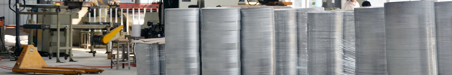
 Production of aluminum round pieces has been completed.
3.2 Case Simulation: Aluminum Heat Spreader Cover for an Electronic Device
- Gereksinimler: Circular cover, çap 200mm, simply supported perimeter, center subjected to max 50N uniform load. Maximum center point deflection ≤ 0.5mm. Operating temperature ≤ 80°C. Requires anodizing.
- Selection Process:
- İşlev: Light-load structural part. Core requirement is stiffness.
- İşlem: Blanking + minor bending. Wide process window. Initial range: 0.5-5.0mm.
- Calculation: Use simplified formula for center deflection of a simply supported circular plate under central load: δ_max ≈ (P * a²) / (16π D) * (3+ν)/(1+ν) (where P is total force, a is radius, D is flexural rigidity, ν is Poisson’s ratio ≈0.33).
- Calculate required flexural rigidity D_req.
- D = E * t³ / [12(1-ν²)]
- Substitute E=69GPa, solve for t³, obtain t_calc ≈ 1.28mm.
- Standardization: Round to standard series: 1.2mm and 1.5mm.
- Evaluation:
- 1.2mm: Calculated deflection ~0.58mm, slightly exceeding requirement. If load is a limit case, may be acceptable or a small peripheral flange could be added for stiffness. Lower material cost.
- 1.5mm: Calculated deflection ~0.30mm, meets requirement with margin. Stiffness is ~1.95x that of 1.2mm, cost ~25% higher.
- Decision: If device demands high reliability and is less cost-sensitive, choose 1.5mm. If under high cost pressure and 0.58mm deflection is visually/functionally acceptable, choose 1.2mm and recommend prototype validation.
4. Advanced Topics and Future Trends
- Anisotropy Effects: Rolling induces directional mechanical properties. Derin çizim için, the plastic strain ratio (r-değeri) ve strain hardening exponent (n değeri) influence thinning and uniformity. For high-demand deep draws, request material r-value (tipik olarak >0.6) and n-value (~0.2 for 1100-O) data.
- Yüzey Kalitesi & Tolerances: Different thicknesses correspond to different surface finishes (E.G., standard mill, çiziksiz) and thickness tolerance grades. High-precision assembly requires tighter tolerances (E.G., ±0,05 mm).
- Proliferation of Finite Element Analysis (FEA): Using software like Abaqus, ANSYS for forming simulation and structural analysis allows precise prediction of fracture, wrinkling risk, and deflection in the design phase, greatly optimizing thickness selection and reducing trial-and-error costs.
- Hybrid Processes & Hafifletme: For applications requiring high stiffness, composite designs like “thinner sheet + stiffening ribs/beads” achieve better lightweighting than simply increasing thickness. This requires more sophisticated tooling and process design.
 Bitmiş alüminyum yuvarlak parçalar
Çözüm
Selecting the correct thickness for 1100 aluminum alloy circles is a comprehensive technical decision integrating materials science, mechanics, süreç mühendisliği, and cost management. There is no universally optimal thickness, only an optimal solution under specific constraints. Successful selection begins with a deep understanding of product function, succeeds by respecting process limits, and concludes with precise control over economics. By following the systematic “Quantify Requirements → Pre-screen for Process → Verify Mechanics → Standardize → Comprehensively Validate” workflow, and leveraging the quantitative data and case analysis in the tables for reference, engineers can make rational, güvenilir, and economical decisions. This maximizes the performance potential of 1100 alüminyum alaşımı, a classic material, ensuring product competitiveness and reliability.