मल्टी-शीट लेमिनेशन में शीट अव्यवस्था से बचना 1070 ट्रांसफार्मर कोर के लिए शुद्ध एल्यूमीनियम डिस्क: इष्टतम गाइड पिन-बुशिंग क्लीयरेंस डिज़ाइन
1. परिचय: अनुप्रयोग पृष्ठभूमि और कोर लेमिनेशन आवश्यकताएँ 1070 ट्रांसफार्मर कोर के लिए शुद्ध एल्यूमीनियम डिस्क
ट्रांसफार्मर कोर विद्युत ऊर्जा रूपांतरण के लिए मुख्य घटक हैं, और उनकी चुंबकीय पारगम्यता और हानि सीधे ट्रांसफार्मर दक्षता निर्धारित करती है. 1070 ट्रांसफार्मर कोर के लिए शुद्ध एल्यूमीनियम डिस्क (अल सामग्री ≥99.7%) अपनी उच्च विद्युत चालकता के कारण छोटे और मध्यम आकार के ट्रांसफार्मर कोर के लिए आदर्श सब्सट्रेट बन गए हैं (≥62% IACS 20℃ पर), कम चुंबकीय हानि (50 हर्ट्ज पर हिस्टैरिसीस हानि ≤0.3W/किग्रा), और उत्कृष्ट लचीलापन-विशेष रूप से उच्च-आवृत्ति के लिए उपयुक्त, कम हानि वाले परिदृश्य (जैसे, नए ऊर्जा वाहन पर लगे ट्रांसफार्मर).
आम तौर पर, ऐसे कोर अपनाते हैं “मल्टी-शीट ब्लैंकिंग और लेमिनेशन” प्रक्रिया: की कुंडल सामग्री 1070 शुद्ध एल्यूमीनियम डिस्क ट्रांसफार्मर कोर के लिए (0.3मिमी मोटी) इन्हें 50-200 मिमी व्यास वाली डिस्क में ब्लैंक किया जाता है, फिर लेमिनेट किया गया (10-50 प्रति लेमिनेशन शीट) कोर कॉलम या योक बनाने के लिए. यहां मुख्य गुणवत्ता संकेतक है लेमिनेशन फैक्टर ≥0.95 (जीबी/टी की विस्तारित आवश्यकता 13789-2022 ट्रांसफार्मर और रिएक्टरों के लिए कोल्ड रोल्ड सिलिकॉन स्टील शीट; लेमिनेशन कारक = वास्तविक लेमिनेशन घनत्व/सैद्धांतिक घनत्व, लेमिनेशन की जकड़न को दर्शाता है).
औद्योगिक अभ्यास में, 35% लेमिनेशन कारक के गैर-अनुपालन से उत्पन्न होता है शीट अव्यवस्था- यानी, आसन्न डिस्क के बीच किनारे की अव्यवस्था >0.03मिमी. इससे कोर के अंदर वायु अंतराल बन जाता है, द्वारा चुंबकीय प्रतिरोध बढ़ाना 15%-20% और नो-लोड हानि द्वारा 8%-12%. मूल कारण का पता लगाना, गाइड पिन और ब्लैंकिंग डाई की झाड़ियों के बीच अनियंत्रित निकासी प्राथमिक ट्रिगर है: अत्यधिक निकासी मार्गदर्शक सटीकता को कम कर देती है, ब्लैंकिंग के दौरान ऊपरी और निचले डाई के बीच गलत संरेखण होता है; अपर्याप्त निकासी, इसके विपरीत, इससे गाइड पिन और बुशिंग घिस जाते हैं और जाम हो जाते हैं, धातु का मलबा उत्पन्न करना जो स्थिति सतह को दूषित करता है. इसलिए, के भौतिक गुणों के आधार पर 1070 ट्रांसफार्मर कोर के लिए शुद्ध एल्यूमीनियम डिस्क और 0.3 मिमी पतली शीट ब्लैंकिंग प्रक्रिया, स्रोत पर शीट अव्यवस्था से बचने के लिए गाइड पिन और बुशिंग के लिए उचित निकासी सीमा निर्धारित करना आवश्यक है.

2. की बुनियादी विशेषता विश्लेषण 1070 ट्रांसफार्मर कोर और मल्टी-शीट लेमिनेशन के लिए शुद्ध एल्युमीनियम डिस्क
(1) की सामग्री और मोटाई विशेषताएँ 1070 ट्रांसफार्मर कोर के लिए शुद्ध एल्यूमीनियम डिस्क (0.3मिमी)
- ब्लैंकिंग स्थिति पर यांत्रिक गुणों का प्रभाव: 1070 ट्रांसफार्मर कोर के लिए शुद्ध एल्यूमीनियम डिस्क केवल HV25-30 की कम कठोरता है, एक लोचदार मापांक E=70GPa, और एक बढ़ाव δ5≥35%. विशेष रूप से, पतली चादरें (0.3मिमी) ब्लैंकिंग के दौरान मार्गदर्शक विचलन के कारण लोचदार विरूपण का खतरा होता है, और यह विकृति अपरिवर्तनीय है - लेमिनेशन के दौरान सीधे तौर पर किनारे की अव्यवस्था का कारण बनती है. उदाहरण के लिए, यदि गाइड पिन और बुशिंग के बीच क्लीयरेंस अत्यधिक है, खाली करने का बल (लगभग 8-12kN, डिस्क व्यास के आधार पर) ऊपरी पासे को 0.02 मिमी तक स्थानांतरित कर देगा, जिससे डिस्क के किनारे पर 0.015 मिमी प्लास्टिक विरूपण हो गया. लेमिनेशन के दौरान संचित अव्यवस्था तब 0.03 मिमी से अधिक हो जाएगी.
- सतह की स्थिति और लेमिनेशन आसंजन: इसके अतिरिक्त, एक प्राकृतिक ऑक्साइड परत (Al₂O₃) की सतह पर 2-5 एनएम आसानी से बन जाता है 1070 ट्रांसफार्मर कोर के लिए शुद्ध एल्यूमीनियम डिस्क. हालांकि इससे इंसुलेशन पर कोई असर नहीं पड़ता है, यह लेमिनेशन के दौरान घर्षण प्रतिरोध को बढ़ाता है. यदि गाइड पिन और झाड़ियों के बीच अत्यधिक निकासी गड़गड़ाहट का कारण बनती है (>0.01मिमी) डिस्क के किनारों पर, ये गड़गड़ाहट आसंजन को और अधिक नुकसान पहुंचाएगी, लेमिनेशन कारक को कम करना 0.96 नीचे को 0.93.
(2) मल्टी-शीट लेमिनेशन के लिए मुख्य आवश्यकताएँ (लेमिनेशन फैक्टर ≥0.95)
- लेमिनेशन कारक की मात्रात्मक परिभाषा: लेमिनेशन फैक्टर K = (वास्तविक लेमिनेशन मोटाई/(एकल-शीट मोटाई × लेमिनेटेड शीटों की संख्या)) × 100%. के लिए 20 की चादरें 1070 ट्रांसफार्मर कोर के लिए शुद्ध एल्यूमीनियम डिस्क (0.3मिमी मोटी), सैद्धांतिक लेमिनेशन मोटाई = 6.0 मिमी. यदि वास्तविक मोटाई = 5.7 मिमी, के=95%; यदि प्रति शीट 0.03 मिमी अव्यवस्था है, का संचित अव्यवस्था 20 शीट = 0.6 मिमी, और वास्तविक प्रभावी लेमिनेशन मोटाई = 5.4 मिमी—परिणामस्वरूप K=90% (गैर-संगत).
- अव्यवस्था और लेमिनेशन कारक के बीच संबंध: परिमित तत्व अनुकरण (अबाकुस) आगे पता चलता है कि जब एकल डिस्क का विस्थापन ≤0.02 मिमी होता है, का लेमिनेशन कारक 20 शीट ≥0.95; जब अव्यवस्था >0.02मिमी, बढ़ती अव्यवस्था के साथ K रैखिक रूप से घटता है (ढलान -1.67%/0.01मिमी), जैसा कि नीचे दी गई तालिका में दिखाया गया है:
| एकल डिस्क का विस्थापन (मिमी) |
0.01 |
0.02 |
0.03 |
0.04 |
0.05 |
| का लेमिनेशन फैक्टर 20 शीट्स (%) |
96.7 |
95.0 |
93.3 |
91.7 |
90.0 |
3. शीट अव्यवस्था पर गाइड पिन-बुशिंग क्लीयरेंस के प्रभाव का तंत्र और मात्रात्मक विश्लेषण
ब्लैंकिंग डाई के गाइड पिन और बुशिंग मुख्य घटक हैं जो ऊपरी और निचले डाई के बीच संरेखण सटीकता सुनिश्चित करते हैं. उनकी मंजूरी (डी) गाइड पिन व्यास द्वारा निर्धारित किया जाता है (डी) और झाड़ी का भीतरी व्यास (डी), यानी, घ=(डी-डी)/2. अत्यधिक और अपर्याप्त निकासी दोनों ही शीट की अव्यवस्था का कारण बनती हैं 1070 ट्रांसफार्मर कोर के लिए शुद्ध एल्यूमीनियम डिस्क, निम्नलिखित विशिष्ट तंत्रों के साथ:
(1) अत्यधिक निकासी (डी>0.015मिमी): “कठोर अव्यवस्था” मार्गदर्शक सटीकता खो जाने के कारण
पहला और महत्वपूर्ण, अत्यधिक निकासी मार्गदर्शक सटीकता को कमजोर करती है, के लिए अग्रणी “कठोर अव्यवस्था.”
- यांत्रिक मॉडल: ब्लैंकिंग के दौरान, ऊपरी पासे पर ब्लैंकिंग बल F लगाया जाता है (के.एन.), गाइड पिन पर एक पार्श्व बल F_side = F×tanθ उत्पन्न करना (θ ब्लैंकिंग एज कोण है, आमतौर पर 5°-8°). के लिए 1070 ट्रांसफार्मर कोर के लिए शुद्ध एल्यूमीनियम डिस्क 100 मिमी के व्यास के साथ, F≈10kN और θ=6°, F_side≈10×tan6°≈1.05kN हैं.
- विस्थापन गणना: गाइड पिन आमतौर पर SUJ2 से बने होते हैं (असर स्टील, ई=206जीपीए). व्यास d=20mm और लंबाई L=150mm वाले गाइड पिन के लिए, सामग्री यांत्रिकी विक्षेपण सूत्र के अनुसार:
Δ= F_side×L³/(3×ई×आई)
जहां I=πd⁴/64 (निष्क्रियता के पल). डेटा को प्रतिस्थापित करना: Δ≈1.05×10³×(150)³/(3×206×10³×π×20⁴/64)≈0.008मिमी.
यदि गाइड पिन-बुशिंग क्लीयरेंस δ=0.02mm है, ऊपरी पासे का कुल विस्थापन = Δ+δ≈0.028 मिमी. इससे रिक्त स्थान का किनारा विस्थापित हो जाता है 1070 ट्रांसफार्मर कोर के लिए शुद्ध एल्यूमीनियम डिस्क लगभग 0.028 मिमी होना, जिसके परिणामस्वरूप लेमिनेशन कारक K≈93.8% प्राप्त हुआ 20 पत्रक (गैर-संगत).

(2) अपर्याप्त निकासी (डी<0.005मिमी): “गतिशील अव्यवस्था” घिसाव और जामिंग के कारण
इसके विपरीत, अपर्याप्त निकासी से घिसाव और जाम लग जाता है, के लिए अग्रणी “गतिशील अव्यवस्था.”
- पहनने का तंत्र: गाइड पिन और बुशिंग H7/h6 फिट को अपनाते हैं (सहनशीलता वर्ग). यदि निकासी <0.005मिमी, ख़राब चिकनाई (इन एल्यूमीनियम शीटों को खाली करने से आसानी से एल्यूमीनियम चिप्स उत्पन्न होते हैं जो ग्रीस को दूषित करते हैं) ओर जाता है “शुष्क घर्षण,” जिससे गाइड पिन की सतह पर खरोंचें आ जाती हैं (गहराई >0.003मिमी).
- अव्यवस्था प्रदर्शन: घिसे हुए गाइड पिन और बुशिंग्स का प्रदर्शन “ठेला-कूदना” व्यवहार: नीचे की ओर गति के दौरान ऊपरी डाई सबसे पहले जाम होती है, फिर अचानक रिलीज हो जाता है. इससे ब्लैंकिंग के दौरान ऊपरी और निचले डाई के बीच 0.02-0.03 मिमी का तात्कालिक संरेखण विचलन होता है, और विचलन यादृच्छिक है - जिससे लेमिनेशन के दौरान इसे ठीक करना मुश्किल हो जाता है 1070 ट्रांसफार्मर कोर के लिए शुद्ध एल्यूमीनियम डिस्क.
(3) उचित क्लीयरेंस रेंज की कटौती: लेमिनेशन फैक्टर के आधार पर थ्रेसहोल्ड ≥0.95
उपरोक्त दोहरे तंत्र के आधार पर, उचित निकासी सीमा संतुलित होनी चाहिए “कठोर अव्यवस्था से बचना” तथा “गतिशील अव्यवस्था को रोकना।” विशेष रूप से, संतुष्ट करना जरूरी है “कुल ऊपरी डाई विस्थापन ≤0.02 मिमी” (एकल का विस्थापन सुनिश्चित करना 1070 ट्रांसफार्मर कोर के लिए शुद्ध एल्यूमीनियम डिस्क ≤0.02 मिमी और K≥0.95), यानी:
Δ+δ≤0.02मिमी
दिया गया Δ≈0.008mm (ब्लैंकिंग बल के कारण गाइड पिन का विक्षेपण), δ≤0.012मिमी.
इस दौरान, अपर्याप्त निकासी के कारण घिसाव से बचने के लिए, जीबी/टी का जिक्र करते हुए 12444-2016 मरो घटक – गाइड पिन, गाइड पिन और बुशिंग के लिए न्यूनतम स्वीकार्य निकासी 0.005 मिमी है (H7/h6 के लिए d=20mm के साथ फिट, गाइड पिन सहनशीलता h6=0/-0.013mm, झाड़ी सहनशीलता H7=+0.021/0मिमी, न्यूनतम निकासी = 0.005 मिमी).
सारांश, गाइड पिन और बुशिंग के बीच की निकासी को 0.005-0.012 मिमी के भीतर नियंत्रित किया जाना चाहिए. यह सीमा एकल की अव्यवस्था सुनिश्चित करती है 1070 ट्रांसफार्मर कोर के लिए शुद्ध एल्यूमीनियम डिस्क ≤0.02 मिमी और लेमिनेशन फैक्टर ≥0.95.

4. क्लीयरेंस नियंत्रण के लिए तकनीकी समाधानों का समर्थन करना (मरना + प्रक्रिया)
शीट की अव्यवस्था से पूरी तरह बचने के लिए केवल गाइड पिन-बुशिंग क्लीयरेंस को नियंत्रित करना अपर्याप्त है 1070 ट्रांसफार्मर कोर के लिए शुद्ध एल्यूमीनियम डिस्क. एक एकीकृत बनाने के लिए डाई संरचना अनुकूलन और प्रक्रिया पैरामीटर समायोजन को संयोजित करना आवश्यक है “मार्गदर्शन-स्थिति-रिक्तीकरण” नियंत्रण प्रणाली:
(1) डाई गाइडिंग सिस्टम अनुकूलन
साथ शुरू करने के लिए, डाई गाइडिंग सिस्टम का अनुकूलन स्थिर निकासी नियंत्रण की नींव रखता है.
- गाइड पिन और बुशिंग की सामग्री और सटीकता:
-
- गाइड पिन: SUJ2 बुझ गया (एचआरसी58-62), सतह खुरदरापन Ra≤0.4μm, बेलनाकारता ≤0.002 मिमी;
-
- बुशिंग्स: SUJ2 बुझ गया (एचआरसी55-58), भीतरी छेद खुरदरापन Ra≤0.2μm, समाक्षीयता ≤0.003मिमी;
-
- फ़िट सहनशीलता: 0.005-0.012 मिमी के भीतर प्रारंभिक निकासी सुनिश्चित करने के लिए H7/h6 फिट को अपनाया जाता है, ब्लैंकिंग सटीकता आवश्यकताओं को अपनाना 1070 ट्रांसफार्मर कोर के लिए शुद्ध एल्यूमीनियम डिस्क.
- गाइड पिन की संख्या और व्यवस्था:
-
- के लिए 1070 ट्रांसफार्मर कोर के लिए शुद्ध एल्यूमीनियम डिस्क 50-200 मिमी के व्यास के साथ, दो गाइड पिन (φ16-20मिमी) उपयोग किया जाता है, ब्लैंकिंग किनारे के बाहर सममित रूप से व्यवस्थित (किनारे से दूरी ≥15मिमी) मार्गदर्शन पर ब्लैंकिंग बल के हस्तक्षेप से बचने के लिए;
-
- “सहायक मार्गदर्शन” (जैसे, स्ट्रिपर प्लेट गाइड पिन) 0.005 मिमी के भीतर ऊपरी और निचले डाई के बीच संरेखण विचलन को और अधिक नियंत्रित करने के लिए जोड़ा गया है.
(2) ब्लैंकिंग प्रक्रिया पैरामीटर मिलान
अगला, प्रक्रिया मापदंडों के संदर्भ में, क्लीयरेंस नियंत्रण के साथ ब्लैंकिंग स्थितियों का मिलान स्थिरता को बढ़ाता है.
- खाली करने की गति: पर नियंत्रित किया गया 100-150 हाई-स्पीड ब्लैंकिंग के कारण गाइड पिन और झाड़ियों के कंपन से बचने के लिए स्ट्रोक/मिनट (जब कंपन आयाम >0.003मिमी, निकासी प्रभाव बढ़ जाता है), की स्थिति स्थिरता सुनिश्चित करना 1070 ट्रांसफार्मर कोर के लिए शुद्ध एल्यूमीनियम डिस्क ब्लैंकिंग के दौरान;
- स्नेहन विधि: “चिकनाई स्प्रे करें” अपनाया गया है (चिकनाई तेल मॉडल: आईएसओ वीजी32, एल्यूमीनियम-विशिष्ट एंटी-वियर एडिटिव्स के साथ). प्रत्येक दिन छिड़काव किया जाता है 500 एल्यूमीनियम चिप उत्पादन को कम करने और घिसाव को निर्देशित करने के लिए ब्लैंकिंग स्ट्रोक, के किनारे की गुणवत्ता की रक्षा करना 1070 ट्रांसफार्मर कोर के लिए शुद्ध एल्यूमीनियम डिस्क;
- लेमिनेशन पोजीशनिंग: खाली करने के बाद, “वैक्यूम सक्शन + पोजीशनिंग पिन” दोहरी स्थिति का उपयोग किया जाता है. पोजिशनिंग पिन का व्यास φ3-5 मिमी है, और पूर्व-छिद्रित छिद्रों के साथ निकासी 1070 ट्रांसफार्मर कोर के लिए शुद्ध एल्यूमीनियम डिस्क मल्टी-शीट लेमिनेशन के दौरान अक्षीय संरेखण सुनिश्चित करने के लिए ≤0.01 मिमी.
(3) निकासी निगरानी और रखरखाव
प्रारंभिक सेटअप से परे, निकासी प्रदर्शन को बनाए रखने के लिए निरंतर निगरानी और रखरखाव भी उतना ही महत्वपूर्ण है.
- ऑनलाइन निगरानी: एक लेजर विस्थापन सेंसर (सटीकता 0.001 मिमी) गाइड पिन के रेडियल रनआउट की वास्तविक समय पर निगरानी करने के लिए बुशिंग के बाहर स्थापित किया गया है. रनआउट होने पर >0.008मिमी (अत्यधिक निकासी का संकेत), गैर-अनुपालन के बड़े पैमाने पर उत्पादन से बचने के लिए मशीन स्वचालित रूप से बंद हो जाती है 1070 ट्रांसफार्मर कोर के लिए शुद्ध एल्यूमीनियम डिस्क;
- नियमित रखरखाव: खाली करने के बाद 100,000 1070 ट्रांसफार्मर कोर के लिए शुद्ध एल्यूमीनियम डिस्क, गाइड पिन और बुशिंग को अलग कर दिया गया है, और क्लीयरेंस को माइक्रोमीटर से मापा जाता है. यदि निकासी >0.015मिमी, झाड़ी को बदल दिया गया है (गाइड पिन में आमतौर पर न्यूनतम घिसाव होता है और इसका पुन: उपयोग किया जा सकता है).
5. औद्योगिक सत्यापन और मामला विश्लेषण
(1) प्रयोगशाला सत्यापन (ट्रांसफार्मर कोर निर्माता से परीक्षण डेटा)
प्रयोगात्मक रूप से घटाई गई क्लीयरेंस रेंज को सत्यापित करना, मानकीकृत नमूनों के साथ प्रयोगशाला परीक्षण किए गए.
लेना “φ120मिमी×0.3मिमी 1070 ट्रांसफार्मर कोर के लिए शुद्ध एल्यूमीनियम डिस्क, 20-शीट लेमिनेशन” परीक्षण वस्तु के रूप में, लेमिनेशन फैक्टर और अव्यवस्था का परीक्षण करने के लिए अलग-अलग गाइड पिन-बुशिंग क्लीयरेंस निर्धारित किए गए थे:
| गाइड पिन-बुशिंग क्लीयरेंस (मिमी) |
एकल डिस्क का विस्थापन (मिमी) |
का लेमिनेशन फैक्टर 20 शीट्स (%) |
कोर नो-लोड हानि (डब्ल्यू/किलो, 50हर्ट्ज) |
| 0.003 (नाकाफी) |
0.025 (Random) |
92.5 |
1.25 |
| 0.008 (उचित) |
0.012 |
96.3 |
1.02 |
| 0.012 (उचित की ऊपरी सीमा) |
0.020 |
95.0 |
1.05 |
| 0.018 (अत्यधिक) |
0.035 |
91.7 |
1.32 |
निष्कर्ष: जब क्लीयरेंस 0.005-0.012 मिमी के भीतर हो, का लेमिनेशन कारक 1070 ट्रांसफार्मर कोर के लिए शुद्ध एल्यूमीनियम डिस्क ≥95% और नो-लोड हानि ≤1.05W/किग्रा, जीबी/टी का अनुपालन 6451-2015 तेल में डूबे पावर ट्रांसफार्मर के लिए तकनीकी पैरामीटर और आवश्यकताएँ.
(2) औद्योगिक अनुप्रयोग मामला (एक नई ऊर्जा वाहन-घुड़सवार ट्रांसफार्मर परियोजना)
औद्योगिक सेटिंग में इन निष्कर्षों के व्यावहारिक चित्रण के लिए, एक नई ऊर्जा वाहन-घुड़सवार ट्रांसफार्मर परियोजना का एक केस अध्ययन प्रस्तुत किया गया है.
एक ऑटोमोबाइल निर्माता द्वारा वाहन पर लगे ट्रांसफार्मर कोर के उत्पादन में, प्रारंभिक अनियंत्रित गाइड पिन-बुशिंग क्लीयरेंस (0.02-0.025मिमी) केवल लेमिनेशन कारक के परिणामस्वरूप 92%-93% के लिये 1070 ट्रांसफार्मर कोर के लिए शुद्ध एल्यूमीनियम डिस्क तथा 30% अत्यधिक कोर हानि. इस पेपर में समाधान अपनाने के बाद:
- H7/h6 फिट वाले गाइड पिन और बुशिंग को बदल दिया गया, 0.008-0.010 मिमी के भीतर नियंत्रण निकासी;
- सहायक मार्गदर्शन और वैक्यूम पोजिशनिंग को जोड़ा गया;
- ऑनलाइन क्लीयरेंस मॉनिटरिंग लागू की गई.
अनुकूलन के बाद, का लेमिनेशन कारक 1070 ट्रांसफार्मर कोर के लिए शुद्ध एल्यूमीनियम डिस्क पर स्थिर हो गया 95.5%-96.2%, और कोर हानि घटकर 1.03W/किलोग्राम हो गई - वाहन पर लगे ट्रांसफार्मर की कम-हानि आवश्यकताओं को पूरा करना. उत्पाद योग्यता दर में वृद्धि हुई 75% प्रति 99%.

6. निष्कर्ष और आउटलुक
(1) मूल निष्कर्ष
प्रमुख निष्कर्षों का सारांश, मल्टी-शीट ब्लैंकिंग और लेमिनेशन के लिए 1070 ट्रांसफार्मर कोर के लिए शुद्ध एल्यूमीनियम डिस्क (0.3मिमी मोटी) लेमिनेशन फैक्टर ≥0.95 के साथ, गाइड पिन और ब्लैंकिंग डाइज़ की झाड़ियों के बीच की निकासी को सख्ती से नियंत्रित किया जाना चाहिए 0.005-0.012मिमी. यह सीमा अत्यधिक निकासी के कारण होने वाली कठोर अव्यवस्था से बचाती है (ऊपरी डाई विस्थापन >0.02मिमी) और अपर्याप्त निकासी के कारण गतिशील अव्यवस्था (पहनना और जमना), एकल डिस्क ≤0.02 मिमी और अनुरूप लेमिनेशन कारक की अव्यवस्था सुनिश्चित करना.
(2) भविष्य के विकास की दिशाएँ
भविष्य की प्रगति की आशा कर रहा हूँ, प्रदर्शन को और बेहतर बनाने के लिए तीन फोकस क्षेत्र उभर कर सामने आए हैं:
- बुद्धिमान मार्गदर्शक प्रणालियाँ: गाइड पिन और बुशिंग की निकासी को वास्तविक समय में समायोजित करने के लिए एआई एल्गोरिदम और पीज़ोइलेक्ट्रिक सेंसर को एकीकृत करें (जैसे, थर्मल विस्तार के माध्यम से मुआवजा पहनें), गतिशील क्लीयरेंस अनुकूलन को साकार करना और लेमिनेशन सटीकता में और सुधार करना 1070 शुद्ध एल्यूमीनियम डिस्क ट्रांसफार्मर कोर के लिए;
- गैपलेस मार्गदर्शक प्रौद्योगिकी: विकास करना “चुंबकीय उत्तोलन मार्गदर्शन” (विद्युत चुम्बकीय बल का उपयोग करके गाइड पिन और बुशिंग का गैर-संपर्क फिट) मार्गदर्शक सटीकता पर क्लीयरेंस के प्रभाव को पूरी तरह से समाप्त करना, की उच्च परिशुद्धता ब्लैंकिंग आवश्यकताओं को अपनाना 1070 ट्रांसफार्मर कोर के लिए शुद्ध एल्यूमीनियम डिस्क;
- सामग्री संशोधन: की सतह को कोट करें 1070 ट्रांसफार्मर कोर के लिए शुद्ध एल्यूमीनियम डिस्क सतह की कठोरता बढ़ाने के लिए 0.5-1μm TiN परत के साथ (एचवी300-400), ब्लैंकिंग गड़गड़ाहट और लेमिनेशन घर्षण को कम करना, और निकासी नियंत्रण की सहनशीलता सीमा का और विस्तार करना.
(3) मूल सिद्धांत
अंत में, इस कार्य में अंतर्निहित मुख्य सिद्धांत यह है कि मल्टी-शीट ब्लैंकिंग और पतली लेमिनेशन 1070 ट्रांसफार्मर कोर के लिए शुद्ध एल्यूमीनियम डिस्क के तालमेल पर ध्यान देना चाहिए “मार्गदर्शन सटीकता-सामग्री गुण-लेमिनेशन आवश्यकताएँ”. नियंत्रण गाइड पिन-बुशिंग क्लीयरेंस नींव है, लेकिन दक्षता हासिल करने के लिए इसे डाई संरचना और प्रक्रिया अनुकूलन के साथ जोड़ा जाना चाहिए, ट्रांसफार्मर कोर का कम हानि वाला उत्पादन.
एल्यूमीनियम सर्कल के गुण:
एल्यूमिनियम सर्कल कई बाजारों के लिए उपयुक्त है, कुकवेयर सहित, मोटर वाहन और प्रकाश उद्योग, आदि।, अच्छे उत्पाद विशेषताओं के लिए धन्यवाद:
- कम अनिसोट्रॉपी, जो गहरी ड्राइंग की सुविधा प्रदान करता है
- मजबूत यांत्रिक गुण
- उच्च और सजातीय गर्मी प्रसार
- तामचीनी होने की क्षमता, PTFE द्वारा कवर किया गया (या अन्य), एनोड किए गए
- अच्छा परावर्तन
- उच्च शक्ति-से-वजन अनुपात
- जंग के लिए स्थायित्व और प्रतिरोध
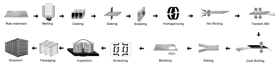
एल्यूमिनियम सर्किल प्रक्रिया
पिंड/मास्टर मिश्र — मेल्टिंग फर्नेस - होल्डिंग फर्नेस — डी.सी.. कास्टर — पत्थर की पटिया —- स्कैल्पर — हॉट रोलिंग मिल - कोल्ड रोलिंग मिल - पंचिंग - एनीलिंग फर्नेस — अंतिम निरीक्षण - पैकिंग — वितरण
- मास्टर मिश्र तैयार करें
- पिघलती भट्टी: मिश्र धातुओं को पिघलने वाली भट्टी में डालें
- डीसी कास्ट एल्यूमीनियम पिंड: माँ को पिंड बनाने के लिए
- एल्यूमीनियम पिंड मिल: सतह और साइड को चिकना बनाने के लिए
- ताप भट्टी
- हॉट रोलिंग मिल: माँ का तार बनाया
- कोल्ड रोलिंग मिल: मदर कॉइल को उस मोटाई के रूप में रोल किया गया था जिसे आप खरीदना चाहते हैं
- छिद्रण प्रक्रिया: आप जो चाहते हैं उसका आकार बनें
- एनीलिंग भट्टी: मिजाज बदलो
- अंतिम निरीक्षण
- पैकिंग: लकड़ी के मामले या लकड़ी के फूस
- वितरण
गुणवत्ता नियंत्रण
आश्वासन नीचे निरीक्षण उत्पादन में किया जाएगा.
- ए. किरण का पता लगाना—आर टी;
- बी. अल्ट्रासोनिक परीक्षण—केन्द्र शासित प्रदेशों;
- सी. चुंबकीय कण परीक्षण-एमटी;
- डी. पैठ परीक्षण-पीटी;
- इ. एड़ी वर्तमान दोष का पता लगाने-ET
1) तेल के दाग से मुक्त रहें, काटने का निशान, समावेश, स्क्रैच, धब्बा, ऑक्साइड मलिनकिरण, ब्रेक, जंग, रोल मार्क्स, गंदगी की धारियाँ, और अन्य दोष जो उपयोग में हस्तक्षेप करेंगे.
2) काली रेखा के बिना सतह, तेज़ बाहर की रेखाओंवालअ, आवधिक दाग, रोलर मुद्रण दोष, जैसे अन्य gko आंतरिक नियंत्रण मानक.
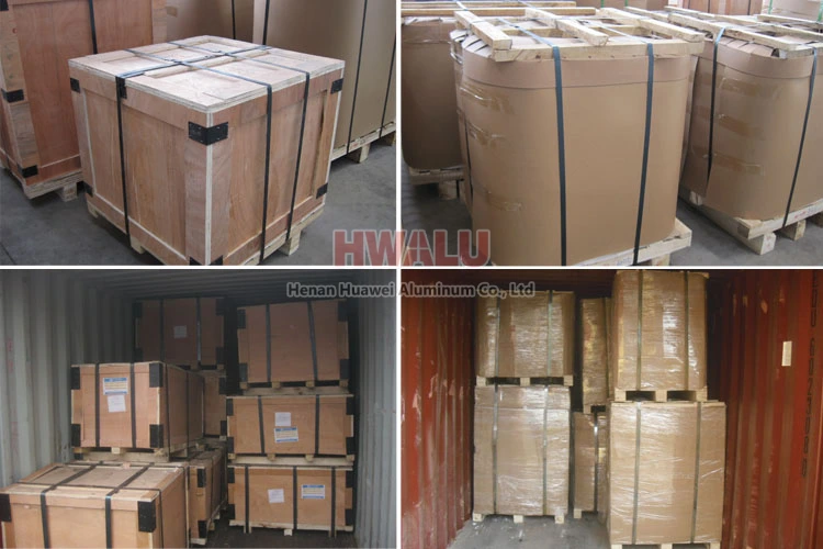
एल्यूमिनियम डिस्क पैकिंग:
एल्यूमिनियम सर्किल निर्यात मानकों द्वारा पैक किया जा सकता है, भूरे रंग के कागज और प्लास्टिक की फिल्म के साथ कवर करना. आखिरकार, एल्यूमिनियम दौर लकड़ी के फूस / लकड़ी के मामले पर तय किया गया है.
- एल्युमिनियम सर्कल के ऊपर ड्रायर्स लगा दें, उत्पादों को सूखा और साफ रखें.
- स्वच्छ प्लास्टिक पेपर का प्रयोग करें, एल्यूमीनियम सर्कल पैक करें, सीलिंग अच्छी रखें.
- सांप की खाल के कागज का प्रयोग करें, प्लास्टिक पेपर की सतह को पैक करें, सीलिंग अच्छी रखें.
- अगला, पैकेजिंग के दो तरीके हैं: लकड़ी के फूस की पैकेजिंग का एक तरीका है, सतह को पैक करने वाले क्रस्टी पेपर का उपयोग करना; दूसरा तरीका लकड़ी के मामले की पैकेजिंग है, सतह को पैक करने वाले लकड़ी के मामले का उपयोग करना.
- आखिरकार, लकड़ी के बक्से की सतह पर स्टील की बेल्ट बिछाएं, लकड़ी के बक्से को तेज और सुरक्षित रखना.
हेनान हुआवेई एल्यूमिनियम का एल्यूमिनियम सर्कल. निर्यात मानक को पूरा करें. प्लास्टिक की फिल्म और भूरे रंग के कागज को ग्राहकों की जरूरतों पर कवर किया जा सकता है. इससे ज्यादा और क्या, डिलीवरी के दौरान उत्पादों को नुकसान से बचाने के लिए लकड़ी के मामले या लकड़ी के फूस को अपनाया जाता है. पैकेजिंग दो प्रकार की होती है, जो आंख से दीवार या आंख से आसमान की ओर हैं. ग्राहक अपनी सुविधा के लिए इनमें से किसी एक को चुन सकते हैं. आम तौर पर बोलना, वहां 2 एक पैकेज में टन, और लोड हो रहा है 18-22 1×20′ कंटेनर में टन, तथा 20-24 1×40′ कंटेनर में टन.
हमारा चयन क्यों?
समय के साथ चलने के लिए, HWALU अपनी प्रतिस्पर्धात्मकता में सुधार के लिए अत्याधुनिक उपकरण और तकनीक पेश करता रहता है. हमेशा केंद्र और ग्राहक के रूप में गुणवत्ता के व्यापार दर्शन का पालन करें, दुनिया के सभी हिस्सों में उच्चतम गुणवत्ता वाले एल्यूमीनियम डिस्क सर्कल श्रृंखला उत्पाद प्रदान करने के लिए. अधिक …