Het vermijden van veldislocatie bij het lamineren van meerdere vellen 1070 Zuiver aluminium schijven voor transformatorkernen: Optimaal ontwerp met speldbusspeling
1. Invoering: Toepassingsachtergrond en kernlamineringsvereisten van 1070 Zuiver aluminium schijven voor transformatorkernen
Transformatorkernen zijn kerncomponenten voor de omzetting van elektrische energie, en hun magnetische permeabiliteit en verlies bepalen rechtstreeks de efficiëntie van de transformator. 1070 zuivere aluminium schijven voor transformatorkernen (Al-gehalte ≥99,7%) zijn vanwege hun hoge elektrische geleidbaarheid ideale substraten geworden voor kleine en middelgrote transformatorkernen (≥62% IACS bij 20℃), laag magnetisch verlies (hysteresisverlies ≤0,3W/kg bij 50Hz), en uitstekende ductiliteit, vooral geschikt voor hoge frequenties, scenario's met weinig verliezen (bijv., nieuwe energie-voertuiggemonteerde transformatoren).
Typisch, Dergelijke kernen nemen de “blanking en laminering van meerdere vellen” proces: spoelmaterialen van 1070 zuivere aluminium schijven voor transformatorkernen (0.3mm dik) worden geperst tot schijven met een diameter van 50-200 mm, vervolgens gelamineerd (10-50 vellen per laminering) om kernkolommen of jukken te vormen. De kernkwaliteitsindicator hier is lamineringsfactor ≥0,95 (uitgebreide eis van GB/T 13789-2022 Koudgewalste siliciumstaalplaten voor transformatoren en reactoren; lamineringsfactor = werkelijke lamineringsdichtheid/theoretische dichtheid, reflecterende lamineringsdichtheid).
In de industriële praktijk, 35% van de niet-naleving van de lamineringsfactor komt voort uit dislocatie van het blad-d.w.z., randdislocatie tussen aangrenzende schijven >0.03mm. Hierdoor ontstaan luchtspleten in de kern, toenemende magnetische weerstand door 15%-20% en nullastverlies door 8%-12%. Het opsporen van de oorzaak, ongecontroleerde speling tussen de geleidepennen en bussen van stansmatrijzen is de belangrijkste trigger: overmatige speling vermindert de geleidingsnauwkeurigheid, waardoor een verkeerde uitlijning ontstaat tussen de bovenste en onderste matrijzen tijdens het stansen; onvoldoende speling, daarentegen, leidt tot slijtage en vastlopen van geleidepennen en bussen, waardoor er metaalresten ontstaan die het positioneringsoppervlak vervuilen. Daarom, gebaseerd op de materiaaleigenschappen van 1070 zuivere aluminium schijven voor transformatorkernen en het blankingproces van 0,3 mm dunne platen, het is noodzakelijk om het redelijke spelingsbereik voor geleidepennen en bussen te bepalen om dislocatie van de plaat bij de bron te voorkomen.

2. Basiskenmerkanalyse van 1070 Schijven van puur aluminium voor transformatorkernen en laminering van meerdere vellen
(1) Materiaal- en diktekenmerken van 1070 Zuiver aluminium schijven voor transformatorkernen (0.3mm)
- Impact van mechanische eigenschappen op de positionering van de blindering: 1070 zuivere aluminium schijven voor transformatorkernen hebben een lage hardheid van slechts HV25-30, een elastische modulus E = 70 GPa, en een verlenging δ5≥35%. Opmerkelijk, de dunne vellen (0.3mm) zijn gevoelig voor elastische vervorming als gevolg van geleidingsafwijkingen tijdens het blinderen, en deze vervorming is onomkeerbaar en veroorzaakt direct dislocatie van de randen tijdens het lamineren. Bijvoorbeeld, als de speling tussen geleidepennen en bussen te groot is, de breekkracht (ongeveer 8-12 kN, afhankelijk van de schijfdiameter) zal de bovenste matrijs met 0,02 mm verschuiven, wat leidt tot een plastische vervorming van 0,015 mm aan de rand van de schijf. De geaccumuleerde dislocatie tijdens het lamineren zal dan groter zijn dan 0,03 mm.
- Oppervlakteconditie en hechting van het laminaat: Aanvullend, een natuurlijke oxidelaag (Al₂O₃) van 2-5nm vormt zich gemakkelijk op het oppervlak van 1070 zuivere aluminium schijven voor transformatorkernen. Hoewel het de isolatie niet beïnvloedt, het verhoogt de wrijvingsweerstand tijdens het lamineren. Als een te grote speling tussen geleidepennen en bussen bramen veroorzaakt (>0.01mm) aan de schijfranden, deze bramen zullen de hechting verder beschadigen, het verminderen van de lamineringsfactor van 0.96 naar beneden 0.93.
(2) Kernvereisten voor het lamineren van meerdere vellen (Lamineringsfactor ≥0,95)
- Kwantitatieve definitie van lamineringsfactor: Lamineringsfactor K = (werkelijke lamineringsdikte/(dikte van één vel x aantal gelamineerde vellen)) × 100%. Voor 20 vellen van 1070 zuivere aluminium schijven voor transformatorkernen (0.3mm dik), de theoretische lamineringsdikte = 6,0 mm. Als de werkelijke dikte = 5,7 mm, K=95%; als er 0,03 mm dislocatie per vel is, de geaccumuleerde ontwrichting van 20 vellen = 0,6 mm, en de werkelijke effectieve lamineringsdikte = 5,4 mm, wat resulteert in K = 90% (niet-conform).
- Relatie tussen dislocatie en lamineringsfactor: Eindige elementensimulatie (ABAQUS) laat verder zien dat wanneer de dislocatie van een enkele schijf ≤0,02 mm, de lamineringsfactor van 20 vellen ≥0,95; wanneer dislocatie >0.02mm, K neemt lineair af met toenemende dislocatie (helling -1,67%/0,01 mm), zoals weergegeven in de onderstaande tabel:
| Dislocatie van enkele schijf (mm) |
0.01 |
0.02 |
0.03 |
0.04 |
0.05 |
| Lamineringsfactor van 20 Lakens (%) |
96.7 |
95.0 |
93.3 |
91.7 |
90.0 |
3. Mechanisme en kwantitatieve analyse van de impact van speling van geleidepenbussen op plaatdislocatie
De geleidepennen en bussen van stansmatrijzen zijn kerncomponenten die de uitlijningsnauwkeurigheid tussen de bovenste en onderste matrijzen garanderen. Hun goedkeuring (D) wordt bepaald door de diameter van de geleidepen (D) en binnendiameter van de bus (D), d.w.z., d=(D-d)/2. Zowel overmatige als onvoldoende speling veroorzaken bladdislocatie 1070 zuivere aluminium schijven voor transformatorkernen, met specifieke mechanismen als volgt:
(1) Overmatige opruiming (D>0.015mm): “Stijve dislocatie” Veroorzaakt door verloren geleidingsnauwkeurigheid
Eerst en vooral, overmatige speling ondermijnt de geleidingsprecisie, leidt tot “stijve dislocatie.”
- Mechanisch model: Tijdens het blanco maken, de bovenste matrijs wordt onderworpen aan stanskracht F (kN), het genereren van een zijdelingse kracht F_side = F×tanθ op de geleidepen (θ is de blinde randhoek, meestal 5°-8°). Voor 1070 zuivere aluminium schijven voor transformatorkernen met een diameter van 100 mm, F≈10kN en θ=6°, zijn F_side≈10×tan6°≈1,05kN.
- Verplaatsingsberekening: Geleidepennen zijn doorgaans gemaakt van SUJ2 (dragend staal, E=206 GPa). Voor een geleidepen met diameter d=20mm en lengte L=150mm, volgens de materiaalmechanische afbuigingsformule:
Δ= F_zijde×L³/(3×E×I)
waarbij I=πd⁴/64 (traagheidsmoment). Het vervangen van de gegevens: Δ≈1,05×10³×(150)³/(3×206×10³×π×20⁴/64)≈0,008 mm.
Als de speling tussen de geleidepen en de bus δ=0,02 mm is, de totale verplaatsing van de bovenste matrijs = Δ+δ≈0,028 mm. Dit veroorzaakt randdislocatie van de blanco 1070 zuivere aluminium schijven voor transformatorkernen ongeveer 0,028 mm bedragen, resulterend in een lamineringsfactor K≈93,8% voor 20 vellen (niet-conform).

(2) Onvoldoende speling (D<0.005mm): “Dynamische dislocatie” Veroorzaakt door slijtage en vastlopen
Omgekeerd, onvoldoende speling veroorzaakt slijtage en vastlopen, leidt tot “dynamische dislocatie.”
- Slijtagemechanisme: Geleidepennen en bussen nemen de H7/h6-passing aan (tolerantie klasse). Indien goedkeuring <0.005mm, slechte smering (Door het blinderen van deze aluminiumplaten ontstaan er gemakkelijk aluminiumspanen die het vet vervuilen) leidt tot “droge wrijving,” waardoor er krassen op het oppervlak van de geleidepen ontstaan (diepte >0.003mm).
- Dislocatieprestaties: Versleten geleidepennen en bussen zijn zichtbaar “jammen-springen” gedrag: de bovenste matrijs blokkeert het eerst tijdens de neerwaartse beweging, komt dan plotseling los. Dit veroorzaakt een onmiddellijke uitlijningsafwijking van 0,02-0,03 mm tussen de bovenste en onderste matrijzen tijdens het blinderen, en de afwijking is willekeurig, waardoor het moeilijk is om deze tijdens het lamineren te corrigeren 1070 zuivere aluminium schijven voor transformatorkernen.
(3) Aftrek van redelijk vrije ruimte: Drempel gebaseerd op lamineringsfactor ≥0,95
Gebaseerd op de bovenstaande dubbele mechanismen, het redelijke spelingsbereik moet in evenwicht zijn “het vermijden van rigide dislocatie” En “het voorkomen van dynamische dislocatie.” Specifiek, het is noodzakelijk om tevreden te stellen “totale verplaatsing van de bovenste matrijs ≤0,02 mm” (zorgen voor ontwrichting van een enkele 1070 schijf van puur aluminium voor transformatorkernen ≤0,02 mm en K≥0,95), d.w.z.:
Δ+δ≤0,02 mm
Gegeven Δ≈0,008 mm (doorbuiging van de geleidepen veroorzaakt door stanskracht), δ≤0,012 mm.
In de tussentijd, om slijtage door onvoldoende speling te voorkomen, verwijzend naar GB/T 12444-2016 Matrijscomponenten – Geleidepennen, de minimaal toegestane speling voor geleidepennen en bussen is 0,005 mm (voor H7/h6 passend met d=20mm, tolerantie geleidepen h6=0/-0,013 mm, tolerantie bus H7=+0,021/0mm, minimale speling = 0,005 mm).
Samengevat, de speling tussen geleidepennen en bussen moet binnen een bereik van 0,005-0,012 mm worden gehouden. Dit bereik zorgt voor dislocatie van een single 1070 schijf van puur aluminium voor transformatorkernen ≤0,02 mm en lamineringsfactor ≥0,95.

4. Ondersteunende technische oplossingen voor vrijgavecontrole (Sterven + Proces)
Het controleren van alleen de speling tussen de geleidepen en de bus is onvoldoende om verplaatsing van de plaat volledig te voorkomen 1070 zuivere aluminium schijven voor transformatorkernen. Het is noodzakelijk om de optimalisatie van de matrijsstructuur en de aanpassing van procesparameters te combineren om een geïntegreerd geheel te vormen “geleiden-positioneren-blanken” controlesysteem:
(1) Optimalisatie van matrijsgeleidingssysteem
Om mee te beginnen, Door het matrijsgeleidingssysteem te optimaliseren wordt de basis gelegd voor een stabiele spelingscontrole.
- Materiaal en nauwkeurigheid van geleidepennen en bussen:
-
- Geleidepennen: SUJ2 uitgedoofd (HRC58-62), oppervlakteruwheid Ra≤0,4μm, cilindriciteit ≤0,002 mm;
-
- Bussen: SUJ2 uitgedoofd (HRC55-58), ruwheid van het binnengat Ra≤0,2 μm, coaxialiteit ≤0,003 mm;
-
- Pastolerantie: Er is een H7/h6-passing toegepast om een initiële speling binnen 0,005-0,012 mm te garanderen, aanpassing aan de blankingnauwkeurigheidseisen van 1070 zuivere aluminium schijven voor transformatorkernen.
- Aantal en opstelling van geleidepennen:
-
- Voor 1070 zuivere aluminium schijven voor transformatorkernen met diameters van 50-200 mm, twee geleidepennen (φ16-20mm) worden gebruikt, symmetrisch aangebracht buiten de stansrand (afstand vanaf rand ≥15mm) om interferentie van de stanskracht op de geleiding te voorkomen;
-
- “Hulpgeleiding” (bijv., geleidepennen van de stripperplaat) wordt toegevoegd om de uitlijningsafwijking tussen de bovenste en onderste matrijzen binnen 0,005 mm verder te controleren.
(2) Matching van blanco procesparameters
Volgende, op het gebied van procesparameters, Het afstemmen van de blanking-omstandigheden met spelingcontrole verbetert de stabiliteit.
- Snelheid van leegmaken: Gecontroleerd bij 100-150 slagen/min om trillingen van geleidepennen en bussen veroorzaakt door blanking op hoge snelheid te voorkomen (wanneer trillingsamplitude >0.003mm, het klaringseffect wordt versterkt), zorgen voor positioneringsstabiliteit van 1070 zuivere aluminium schijven voor transformatorkernen tijdens het blanco maken;
- Smeermethode: “Spray smering” wordt aangenomen (smeeroliemodel: ISO VG32, met aluminiumspecifieke anti-slijtage additieven). Er wordt elke keer gespoten 500 stansslagen om de vorming van aluminiumspanen en geleidingsslijtage te verminderen, het beschermen van de randkwaliteit van 1070 zuivere aluminium schijven voor transformatorkernen;
- Positionering van lamineren: Na het blanco maken, “vacuüm zuiging + positioneringspinnen” Er wordt gebruik gemaakt van dubbele positionering. De positioneringspinnen hebben een diameter van φ3-5 mm, en de speling met de voorgeponste gaten van 1070 zuivere aluminium schijven voor transformatorkernen ≤0,01 mm om axiale uitlijning te garanderen tijdens het lamineren van meerdere vellen.
(3) Controle en onderhoud van opruiming
Verder dan de initiële installatie, voortdurende monitoring en onderhoud zijn evenzeer van cruciaal belang om de opruimingsprestaties op peil te houden.
- Online-monitoring: Een laserverplaatsingssensor (nauwkeurigheid 0,001 mm) wordt buiten de bus geïnstalleerd om in realtime de radiale slingering van de geleidepen te bewaken. Wanneer uitloop >0.008mm (wijst op een te grote speling), de machine stopt automatisch om massaproductie van niet-conforme producten te voorkomen 1070 zuivere aluminium schijven voor transformatorkernen;
- Regelmatig onderhoud: Na het blanco maken 100,000 1070 zuivere aluminium schijven voor transformatorkernen, de geleidepennen en bussen zijn gedemonteerd, en de speling wordt gemeten met een micrometer. Indien goedkeuring >0.015mm, de bus wordt vervangen (geleidepennen vertonen doorgaans minimale slijtage en kunnen worden hergebruikt).
5. Industriële verificatie en casusanalyse
(1) Laboratoriumverificatie (Testgegevens van een fabrikant van transformatorkernen)
Om het afgeleide klaringsbereik experimenteel te valideren, laboratoriumtests werden uitgevoerd met gestandaardiseerde monsters.
Nemen “φ120 mm × 0,3 mm 1070 zuivere aluminium schijven voor transformatorkernen, 20-lamineren van vellen” als testobject, Er werden verschillende spelingen voor de geleidepenbussen ingesteld om de lamineringsfactor en dislocatie te testen:
| Speling van geleidepenbus (mm) |
Dislocatie van enkele schijf (mm) |
Lamineringsfactor van 20 Lakens (%) |
Kernverlies bij nullast (W/kg, 50Hz) |
| 0.003 (Onvoldoende) |
0.025 (willekeurig) |
92.5 |
1.25 |
| 0.008 (Redelijk) |
0.012 |
96.3 |
1.02 |
| 0.012 (Bovengrens van redelijk) |
0.020 |
95.0 |
1.05 |
| 0.018 (Excessief) |
0.035 |
91.7 |
1.32 |
Conclusie: Wanneer de speling binnen 0,005-0,012 mm ligt, de lamineringsfactor van 1070 zuivere aluminium schijven voor transformatorkernen ≥95% en verlies bij nullast ≤1,05W/kg, voldoen aan GB/T 6451-2015 Technische parameters en vereisten voor in olie ondergedompelde stroomtransformatoren.
(2) Industriële toepassingscasus (Een nieuw energievoertuiggemonteerd transformatorproject)
Voor een praktische illustratie van deze bevindingen in industriële omgevingen, er wordt een casestudy gepresenteerd van een nieuw energievoertuiggemonteerd transformatorproject.
Bij de productie van op voertuigen gemonteerde transformatorkernen door een autofabrikant, aanvankelijke ongecontroleerde speling tussen de geleidepen en de bus (0.02-0.025mm) resulteerde in een lamineringsfactor van slechts 92%-93% voor 1070 zuivere aluminium schijven voor transformatorkernen En 30% overmatig kernverlies. Na het adopteren van de oplossingen in dit document:
- Geleidepennen en bussen met H7/H6-passing zijn vervangen, het regelen van de speling binnen 0,008-0,010 mm;
- Hulpgeleiding en vacuümpositionering werden toegevoegd;
- Er werd online toezicht op de opruiming geïmplementeerd.
Na optimalisatie, de lamineringsfactor van 1070 zuivere aluminium schijven voor transformatorkernen gestabiliseerd op 95.5%-96.2%, en het kernverlies daalde tot 1,03 W/kg, wat voldoet aan de eisen met laag verlies van op voertuigen gemonteerde transformatoren. Het productkwalificatiepercentage steeg van 75% naar 99%.

6. Conclusies en vooruitzichten
(1) Kernconclusies
Een samenvatting van de belangrijkste bevindingen, voor het blanco maken van meerdere vellen en het lamineren van 1070 zuivere aluminium schijven voor transformatorkernen (0.3mm dik) met een lamineringsfactor ≥0,95, de speling tussen de geleidepennen en bussen van de stansmatrijzen moet binnen strikt worden gecontroleerd 0.005-0.012mm. Dit bereik vermijdt zowel stijve dislocatie veroorzaakt door overmatige speling (verplaatsing van de bovenste matrijs >0.02mm) en dynamische dislocatie veroorzaakt door onvoldoende speling (slijtage en vastlopen), zorgen voor dislocatie van een enkele schijf ≤0,02 mm en conforme lamineringsfactor.
(2) Toekomstige ontwikkelingsrichtingen
Vooruitkijkend naar toekomstige ontwikkelingen, Er komen drie aandachtsgebieden naar voren om de prestaties verder te verbeteren:
- Intelligente geleidingssystemen: Integreer AI-algoritmen en piëzo-elektrische sensoren om in realtime de speling van geleidepennen en bussen aan te passen (bijv., slijtagecompensatie door thermische uitzetting), het realiseren van dynamische spelingoptimalisatie en het verder verbeteren van de lamineringsnauwkeurigheid van 1070 zuiver aluminium schijven voor transformatorkernen;
- Gapless geleidingstechnologie: Ontwikkelen “magnetische levitatiegeleiding” (contactloze pasvorm van geleidepennen en bussen met behulp van elektromagnetische kracht) om de impact van speling op de geleidingsnauwkeurigheid volledig te elimineren, aanpassing aan de hogere precisie-blankingsvereisten van 1070 zuivere aluminium schijven voor transformatorkernen;
- Materiële wijziging: Bestrijk het oppervlak van 1070 zuivere aluminium schijven voor transformatorkernen met een TiN-laag van 0,5-1 μm om de oppervlaktehardheid te vergroten (HV300-400), vermindering van bramen en wrijving bij het lamineren, en het verder uitbreiden van het tolerantiebereik van de spelingscontrole.
(3) Kernprincipe
Uiteindelijk, Het kernprincipe dat aan dit werk ten grondslag ligt, is het blankeren en lamineren van meerdere vellen 1070 zuivere aluminium schijven voor transformatorkernen moet zich richten op de synergie van “leidende nauwkeurigheid-materiaaleigenschappen-laminatie-eisen”. Het beheersen van de speling tussen de geleidepen en bussen is de basis, maar het moet worden gecombineerd met matrijsstructuur en procesoptimalisatie om efficiënt te zijn, productie met lage verliezen van transformatorkernen.
Eigenschappen van de aluminium cirkel:
Aluminium cirkel is geschikt voor vele markten, inclusief kookgerei, auto- en verlichtingsindustrie, enz., dankzij goede producteigenschappen:
- Lage anisotropie, wat het dieptrekken vergemakkelijkt
- Sterke mechanische eigenschappen
- Hoge en homogene warmteverspreiding
- Mogelijkheid om te emailleren, bedekt met PTFE (of anderen), geanodiseerd
- Goede reflectiviteit
- Hoge sterkte-gewichtsverhouding
- Duurzaamheid en weerstand tegen corrosie
Aluminium cirkels proces
Ingots/Master-legeringen — Smeltoven – Houdoven — DC. Caster — Plaat —- Scalper — Warmwalserij – Koudwalserij – Ponsen – Gloeioven — Eindinspectie – verpakking — Levering
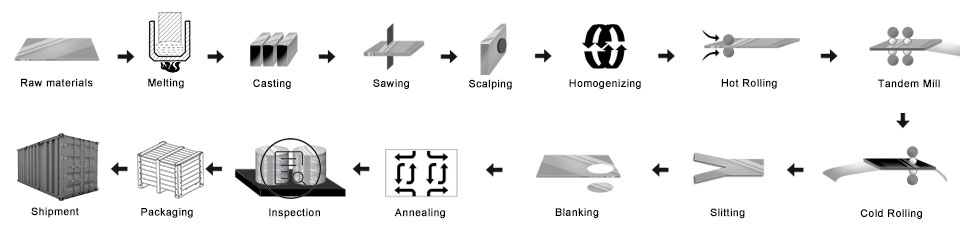
- Bereid de masterlegeringen voor
- Smeltoven: plaats de legeringen in de smeltoven
- D.C. gegoten aluminium staaf: Om de moederbaar te maken
- Frees de aluminium staaf: om het oppervlak en de zijkant glad te maken
- Verwarming oven
- Warmwalserij: de moederspoel gemaakt
- Koudewalserij: de moederspoel werd gerold in de dikte die u wilt kopen
- Ponsen proces: word de maat die je wilt
- Gloeioven: verander het humeur
- Eind inspectie
- Inpakken: houten kist of houten pallet
- Levering
Kwaliteitscontrole
Zekerheid Onderstaande inspectie zal tijdens de productie worden uitgevoerd.
- A. straal detectie—RT;
- B. ultrasoon testen—UT;
- C. Magnetische deeltjestesten-MT;
- D. penetratietesten-PT;
- e. wervelstroomfoutdetectie-ET
1) Wees vrij van olievlekken, Deuk, Inclusie, Krassen, Vlek, Oxideverkleuring, Pauzes, Corrosie, Rolmarkeringen, Vuil strepen, en andere gebreken die het gebruik hinderen.
2) Oppervlak zonder zwarte lijn, zuiver gesneden, periodieke vlek, defecten bij het afdrukken van rollen, zoals andere interne controlenormen van de gko.
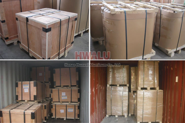
Aluminium schijven verpakking:
Aluminiumcirkels kunnen volgens exportnormen worden verpakt, bedekken met bruin papier en plastic folie. Eindelijk, de Aluminium Round wordt op een houten pallet/houten kist bevestigd.
- Plaats de drogers naast de aluminium cirkel, houd de producten droog en schoon.
- Gebruik schoon plastic papier, pak de aluminium cirkel in, goede afdichting behouden.
- Gebruik het slangenleerpapier, pak het oppervlak van het plastic papier in, goede afdichting behouden.
- Volgende, Er zijn twee manieren van verpakken: Eén manier is het verpakken van houten pallets, gebruik het knapperige papier dat het oppervlak bedekt; Een andere manier is het verpakken van houten kistjes, met behulp van de houten kist die het oppervlak inpakt.
- Eindelijk, leg de stalen riem op het oppervlak van de houten kist, het houden van de houten kistvastheid en veiligheid.
Aluminium cirkel van Henan Huawei Aluminium. voldoen aan de exportnorm. Plastic folie en bruin papier kunnen naar wens van de klant worden afgedekt. Bovendien, Er wordt een houten kist of houten pallet gebruikt om producten tijdens de levering tegen schade te beschermen. Er zijn twee soorten verpakkingen, die oog in oog staan met de muur of oog naar de lucht. Klanten kunnen voor hun gemak een van beide kiezen. In het algemeen, er zijn 2 ton in één pakket, en laden 18-22 ton in 1×20′ container, En 20-24 ton in 1×40′ container.
Waarom voor ons kiezen?
Om met de tijd mee te gaan, HWALU blijft de modernste apparatuur en techniek introduceren om zijn concurrentiepositie te verbeteren. Houd u altijd eerst aan de bedrijfsfilosofie van kwaliteit als centrum en klant, om producten uit de aluminium schijfcirkelserie van de hoogste kwaliteit aan alle delen van de wereld te leveren. Meer …