Evitando o deslocamento da folha na laminação de múltiplas folhas de 1070 Discos de alumínio puro para núcleos de transformadores: Projeto ideal de folga entre pino e bucha-guia
1. Introdução: Antecedentes da aplicação e requisitos básicos de laminação de 1070 Discos de alumínio puro para núcleos de transformadores
Os núcleos do transformador são componentes essenciais para conversão de energia elétrica, e sua permeabilidade magnética e perda determinam diretamente a eficiência do transformador. 1070 discos de alumínio puro para núcleos de transformadores (Conteúdo de Al ≥99,7%) tornaram-se substratos ideais para núcleos de transformadores de pequeno e médio porte devido à sua alta condutividade elétrica (≥62% IACS a 20℃), baixa perda magnética (perda de histerese ≤0,3W/kg a 50Hz), e excelente ductilidade - especialmente adequado para alta frequência, cenários de baixa perda (por exemplo, novos transformadores montados em veículos de energia).
Tipicamente, tais núcleos adotam o “blanking e laminação de múltiplas folhas” processo: materiais de bobina de 1070 discos de alumínio puro para núcleos de transformadores (0.3mm de espessura) são moldados em discos com diâmetros de 50-200 mm, então laminado (10-50 folhas por laminação) para formar colunas centrais ou jugos. O principal indicador de qualidade aqui é fator de laminação ≥0,95 (exigência estendida de GB/T 13789-2022 Chapas de aço silício laminadas a frio para transformadores e reatores; fator de laminação = densidade de laminação real/densidade teórica, refletindo a estanqueidade da laminação).
Na prática industrial, 35% da não conformidade do fator de laminação decorre de deslocamento de folha- ou seja, deslocamento de borda entre discos adjacentes >0.03milímetros. Isso cria lacunas de ar dentro do núcleo, aumentando a resistência magnética por 15%-20% e perda sem carga por 8%-12%. Rastreando a causa raiz, folga descontrolada entre os pinos-guia e as buchas das matrizes cegas é o principal gatilho: folga excessiva reduz a precisão da orientação, causando desalinhamento entre as matrizes superior e inferior durante o corte; folga insuficiente, por contraste, leva ao desgaste e travamento dos pinos-guia e buchas, gerando detritos metálicos que contaminam a superfície de posicionamento. Portanto, com base nas propriedades do material 1070 discos de alumínio puro para núcleos de transformadores e o processo de apagamento de folhas finas de 0,3 mm, é necessário determinar a faixa de folga razoável para pinos-guia e buchas para evitar deslocamento da folha na fonte.

2. Análise de características básicas de 1070 Discos de alumínio puro para núcleos de transformadores e laminação de múltiplas folhas
(1) Características de material e espessura de 1070 Discos de alumínio puro para núcleos de transformadores (0.3milímetros)
- Impacto das propriedades mecânicas no posicionamento do blanking: 1070 discos de alumínio puro para núcleos de transformadores têm uma dureza baixa de apenas HV25-30, um módulo de elasticidade E=70GPa, e um alongamento δ5≥35%. Notavelmente, as folhas finas (0.3milímetros) são propensos à deformação elástica devido ao desvio de orientação durante a supressão, e esta deformação é irreversível - causando diretamente o deslocamento da borda durante a laminação. Por exemplo, se a folga entre os pinos-guia e as buchas for excessiva, a força de apagamento (aproximadamente 8-12kN, dependendo do diâmetro do disco) deslocará a matriz superior em 0,02 mm, levando a uma deformação plástica de 0,015 mm na borda do disco. O deslocamento acumulado durante a laminação excederá então 0,03 mm.
- Condição da superfície e adesão da laminação: Adicionalmente, uma camada de óxido natural (Al₂O₃) de 2-5 nm se forma facilmente na superfície de 1070 discos de alumínio puro para núcleos de transformadores. Embora não afete o isolamento, aumenta a resistência ao atrito durante a laminação. Se a folga excessiva entre os pinos-guia e as buchas causar rebarbas (>0.01milímetros) nas bordas do disco, essas rebarbas danificarão ainda mais a adesão, reduzindo o fator de laminação de 0.96 para baixo 0.93.
(2) Requisitos básicos para laminação de múltiplas folhas (Fator de Laminação ≥0,95)
- Definição quantitativa de fator de laminação: Fator de laminação K = (espessura real da laminação/(espessura de folha única × número de folhas laminadas)) × 100%. Para 20 folhas de 1070 discos de alumínio puro para núcleos de transformadores (0.3mm de espessura), a espessura teórica da laminação = 6,0 mm. Se a espessura real = 5,7 mm, K=95%; se houver deslocamento de 0,03 mm por folha, o deslocamento acumulado de 20 folhas = 0,6 mm, e a espessura efetiva real da laminação = 5,4 mm - resultando em K = 90% (não conforme).
- Relação entre deslocamento e fator de laminação: Simulação de elementos finitos (ÁBACO) mostra ainda que quando o deslocamento de um único disco ≤0,02mm, o fator de laminação de 20 folhas ≥0,95; quando luxação >0.02milímetros, K diminui linearmente com o aumento do deslocamento (inclinação -1,67%/0,01mm), como mostrado na tabela abaixo:
| Luxação de disco único (milímetros) |
0.01 |
0.02 |
0.03 |
0.04 |
0.05 |
| Fator de Laminação de 20 Folhas (%) |
96.7 |
95.0 |
93.3 |
91.7 |
90.0 |
3. Mecanismo e análise quantitativa do impacto da folga do pino-guia no deslocamento da chapa
Os pinos-guia e as buchas das matrizes de corte são componentes essenciais que garantem a precisão do alinhamento entre as matrizes superiores e inferiores. Sua liberação (d) é determinado pelo diâmetro do pino guia (d) e diâmetro interno da bucha (D), ou seja, d =(D-d)/2. Folga excessiva e insuficiente causam deslocamento da folha 1070 discos de alumínio puro para núcleos de transformadores, com mecanismos específicos como segue:
(1) Liberação excessiva (d>0.015milímetros): “Luxação Rígida” Causado pela perda de precisão de orientação
Em primeiro lugar, folga excessiva prejudica a precisão da orientação, levando a “luxação rígida.”
- Modelo mecânico: Durante a supressão, a matriz superior está sujeita à força de corte F (kN), gerando uma força lateral F_side = F×tanθ no pino guia (θ é o ângulo da borda cega, geralmente 5°-8°). Para 1070 discos de alumínio puro para núcleos de transformadores com diâmetro de 100mm, F≈10kN e θ=6°, são F_side≈10×tan6°≈1,05kN.
- Cálculo de deslocamento: Os pinos-guia são normalmente feitos de SUJ2 (rolamento de aço, E=206GPa). Para um pino guia com diâmetro d=20mm e comprimento L=150mm, de acordo com a fórmula de deflexão da mecânica dos materiais:
Δ= F_lado×L³/(3×E×I)
onde eu=πd⁴/64 (momento de inércia). Substituindo os dados: Δ≈1,05×10³×(150)³/(3×206×10³×π×20⁴/64)≈0,008 mm.
Se a folga da bucha do pino-guia δ = 0,02 mm, o deslocamento total da matriz superior = Δ+δ≈0,028mm. Isso causa deslocamento da borda do blanked 1070 discos de alumínio puro para núcleos de transformadores ser aproximadamente 0,028 mm, resultando em um fator de laminação K≈93,8% para 20 folhas (não conforme).

(2) Folga insuficiente (d<0.005milímetros): “Luxação Dinâmica” Causado por desgaste e bloqueio
Por outro lado, folga insuficiente provoca desgaste e emperramento, levando a “deslocamento dinâmico.”
- Mecanismo de desgaste: Pinos-guia e buchas adotam ajuste H7/h6 (classe de tolerância). Se liberação <0.005milímetros, má lubrificação (o apagamento dessas folhas de alumínio gera facilmente lascas de alumínio que contaminam a graxa) leva a “fricção seca,” causando arranhões na superfície do pino-guia (profundidade >0.003milímetros).
- Desempenho de deslocamento: Exibição de pinos-guia e buchas desgastadas “salto” comportamento: a matriz superior emperra primeiro durante o movimento descendente, então de repente libera. Isso causa um desvio de alinhamento instantâneo de 0,02-0,03 mm entre as matrizes superior e inferior durante o blanking, e o desvio é aleatório - dificultando a correção durante a laminação de 1070 discos de alumínio puro para núcleos de transformadores.
(3) Dedução da faixa de folga razoável: Limite baseado no fator de laminação ≥0,95
Com base nos mecanismos duplos acima, a faixa de folga razoável deve equilibrar “evitando deslocamento rígido” e “evitando deslocamento dinâmico.” Especificamente, é necessário satisfazer “deslocamento total da matriz superior ≤0,02 mm” (garantindo o deslocamento de um único 1070 disco de alumínio puro para núcleos de transformadores ≤0,02 mm e K≥0,95), ou seja:
Δ+δ≤0,02 mm
Dado Δ≈0,008 mm (deflexão do pino-guia causada pela força de supressão), δ≤0,012 mm.
Enquanto isso, para evitar desgaste devido à folga insuficiente, referindo-se a GB/T 12444-2016 Componentes da matriz – Pinos guia, a folga mínima permitida para pinos-guia e buchas é de 0,005 mm (para H7/h6 ajuste com d=20mm, tolerância do pino guia h6 = 0/-0,013 mm, tolerância da bucha H7=+0,021/0mm, folga mínima = 0,005 mm).
Resumindo, a folga entre os pinos-guia e as buchas deve ser controlada entre 0,005-0,012 mm. Esta faixa garante o deslocamento de um único 1070 disco de alumínio puro para núcleos de transformadores ≤0,02mm e fator de laminação ≥0,95.

4. Soluções técnicas de suporte para controle de liberação (Morrer + Processo)
Controlar apenas a folga entre o pino guia e a bucha é insuficiente para evitar completamente o deslocamento da folha 1070 discos de alumínio puro para núcleos de transformadores. É necessário combinar a otimização da estrutura da matriz e o ajuste dos parâmetros do processo para formar um sistema integrado “orientação-posicionamento-branco” sistema de controle:
(1) Otimização do sistema de guiamento de matrizes
Para começar, otimizar o sistema de guiamento da matriz estabelece a base para um controle de folga estável.
- Material e precisão dos pinos-guia e buchas:
-
- Pinos guia: SUJ2 extinto (HRC58-62), rugosidade superficial Ra≤0,4μm, cilindricidade ≤0,002 mm;
-
- Buchas: SUJ2 extinto (HRC55-58), rugosidade do furo interno Ra≤0,2μm, coaxialidade ≤0,003 mm;
-
- Tolerância de ajuste: O ajuste H7/h6 é adotado para garantir folga inicial entre 0,005-0,012 mm, adaptando-se aos requisitos de precisão de apagamento de 1070 discos de alumínio puro para núcleos de transformadores.
- Número e disposição dos pinos-guia:
-
- Para 1070 discos de alumínio puro para núcleos de transformadores com diâmetros de 50-200mm, dois pinos guia (φ16-20mm) são usados, dispostos simetricamente fora da borda cega (distância da borda ≥15mm) para evitar interferência da força de supressão na orientação;
-
- “Orientação auxiliar” (por exemplo, pinos guia da placa descascadora) é adicionado para controlar ainda mais o desvio de alinhamento entre as matrizes superior e inferior dentro de 0,005 mm.
(2) Supressão de correspondência de parâmetros de processo
Próximo, em termos de parâmetros de processo, combinar condições de blanking com controle de folga aumenta a estabilidade.
- Velocidade de apagamento: Controlado em 100-150 cursos/min para evitar vibração dos pinos-guia e buchas causadas pela supressão de alta velocidade (quando amplitude de vibração >0.003milímetros, o efeito de depuração é amplificado), garantindo a estabilidade do posicionamento 1070 discos de alumínio puro para núcleos de transformadores durante a supressão;
- Método de lubrificação: “Lubrificação por spray” é adotado (modelo de óleo lubrificante: ISO VG32, com aditivos antidesgaste específicos para alumínio). A pulverização é realizada a cada 500 cursos de supressão para reduzir a geração de cavacos de alumínio e o desgaste da guia, protegendo a qualidade da borda de 1070 discos de alumínio puro para núcleos de transformadores;
- Posicionamento de laminação: Depois de apagar, “sucção a vácuo + pinos de posicionamento” posicionamento duplo é usado. Os pinos de posicionamento têm um diâmetro de φ3-5mm, e a folga com os furos pré-perfurados de 1070 discos de alumínio puro para núcleos de transformadores ≤0,01 mm para garantir o alinhamento axial durante a laminação de múltiplas folhas.
(3) Monitoramento e Manutenção de Liberação
Além da configuração inicial, monitoramento e manutenção contínuos são igualmente críticos para sustentar o desempenho da liberação.
- Monitoramento on-line: Um sensor de deslocamento a laser (precisão 0,001 mm) é instalado fora da bucha para monitorar em tempo real o desvio radial do pino guia. Quando esgotado >0.008milímetros (indicando folga excessiva), a máquina para automaticamente para evitar a produção em massa de produtos não conformes 1070 discos de alumínio puro para núcleos de transformadores;
- Manutenção regular: Depois de apagar 100,000 1070 discos de alumínio puro para núcleos de transformadores, os pinos-guia e as buchas são desmontados, e a folga é medida com um micrômetro. Se liberação >0.015milímetros, a bucha é substituída (os pinos-guia geralmente apresentam desgaste mínimo e podem ser reutilizados).
5. Verificação Industrial e Análise de Caso
(1) Verificação Laboratorial (Dados de teste de um fabricante de núcleo de transformador)
Para validar experimentalmente a faixa de folga deduzida, testes laboratoriais foram realizados com amostras padronizadas.
Tirando “φ120 mm × 0,3 mm 1070 discos de alumínio puro para núcleos de transformadores, 20-laminação de folhas” como o objeto de teste, diferentes folgas da bucha do pino-guia foram definidas para testar o fator de laminação e o deslocamento:
| Folga Pino-Bucha Guia (milímetros) |
Luxação de disco único (milímetros) |
Fator de Laminação de 20 Folhas (%) |
Perda sem carga principal (W/kg, 50Hz) |
| 0.003 (Insuficiente) |
0.025 (aleatório) |
92.5 |
1.25 |
| 0.008 (Razoável) |
0.012 |
96.3 |
1.02 |
| 0.012 (Limite Superior de Razoável) |
0.020 |
95.0 |
1.05 |
| 0.018 (Excessivo) |
0.035 |
91.7 |
1.32 |
Conclusão: Quando a folga estiver entre 0,005-0,012 mm, o fator de laminação de 1070 discos de alumínio puro para núcleos de transformadores ≥95% e perda sem carga ≤1,05W/kg, em conformidade com GB/T 6451-2015 Parâmetros técnicos e requisitos para transformadores de potência imersos em óleo.
(2) Caso de aplicação industrial (Um novo projeto de transformador montado em veículo de energia)
Para uma ilustração prática dessas descobertas em ambientes industriais, é apresentado um estudo de caso de um novo projeto de transformador montado em veículo de energia.
Na produção de núcleos de transformadores montados em veículos por um fabricante de automóveis, folga inicial não controlada da bucha do pino-guia (0.02-0.025milímetros) resultou em um fator de laminação de apenas 92%-93% para 1070 discos de alumínio puro para núcleos de transformadores e 30% perda excessiva de núcleo. Depois de adotar as soluções neste documento:
- Pinos-guia e buchas com ajuste H7/h6 foram substituídos, controlando a folga dentro de 0,008-0,010 mm;
- Orientação auxiliar e posicionamento a vácuo foram adicionados;
- O monitoramento de liberação online foi implementado.
Após a otimização, o fator de laminação de 1070 discos de alumínio puro para núcleos de transformadores estabilizado em 95.5%-96.2%, e a perda do núcleo diminuiu para 1,03 W/kg – atendendo aos requisitos de baixa perda de transformadores montados em veículos. A taxa de qualificação do produto aumentou de 75% para 99%.

6. Conclusões e perspectivas
(1) Conclusões principais
Resumindo as principais conclusões, para corte e laminação de múltiplas folhas de 1070 discos de alumínio puro para núcleos de transformadores (0.3mm de espessura) com fator de laminação ≥0,95, a folga entre os pinos-guia e as buchas das matrizes de corte deve ser rigorosamente controlada dentro 0.005-0.012milímetros. Esta faixa evita deslocamentos rígidos causados por folga excessiva (deslocamento da matriz superior >0.02milímetros) e deslocamento dinâmico causado por folga insuficiente (desgaste e emperramento), garantindo deslocamento de um único disco ≤0,02 mm e fator de laminação compatível.
(2) Direções de Desenvolvimento Futuro
Olhando para os avanços futuros, surgem três áreas de foco para melhorar ainda mais o desempenho:
- Sistemas de orientação inteligentes: Integre algoritmos de IA e sensores piezoelétricos para ajustar em tempo real a folga dos pinos-guia e buchas (por exemplo, compensação de desgaste via expansão térmica), realizando a otimização dinâmica da folga e melhorando ainda mais a precisão da laminação de 1070 puro discos de alumínio para núcleos de transformadores;
- Tecnologia de orientação sem intervalos: Desenvolver “guia de levitação magnética” (ajuste sem contato de pinos-guia e buchas usando força eletromagnética) para eliminar completamente o impacto da folga na precisão da orientação, adaptando-se aos requisitos de supressão de maior precisão de 1070 discos de alumínio puro para núcleos de transformadores;
- Modificação de materiais: Cubra a superfície de 1070 discos de alumínio puro para núcleos de transformadores com uma camada de TiN de 0,5-1 μm para aumentar a dureza da superfície (HV300-400), reduzindo rebarbas de corte e atrito de laminação, e expandindo ainda mais a faixa de tolerância do controle de folga.
(3) Princípio Fundamental
Em última análise, o princípio fundamental subjacente a este trabalho é que a supressão e laminação de múltiplas folhas de folhas finas 1070 discos de alumínio puro para núcleos de transformadores deve se concentrar na sinergia de “orientando requisitos de precisão-propriedades do material-laminação”. Controlar a folga da bucha do pino-guia é a base, mas deve ser combinado com a estrutura da matriz e a otimização do processo para alcançar eficiência, produção de baixa perda de núcleos de transformadores.
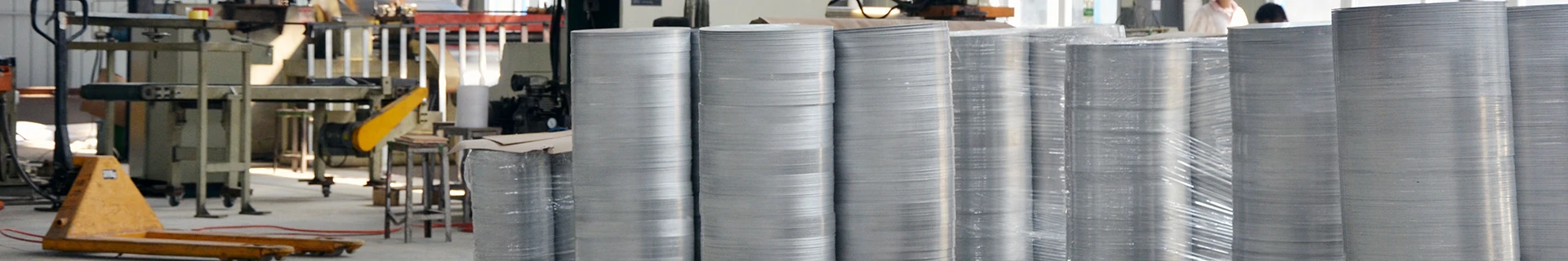
Propriedades do círculo de alumínio:
O círculo de alumínio é adequado para muitos mercados, incluindo panelas, indústrias automotiva e de iluminação, etc., graças às boas características do produto:
- Baixa anisotropia, o que facilita o desenho profundo
- Propriedades mecânicas fortes
- Difusão de calor alta e homogênea
- Capacidade de ser esmaltado, coberto por PTFE (ou outros), anodizado
- Boa refletividade
- Alta relação resistência-peso
- Durabilidade e resistência à corrosão
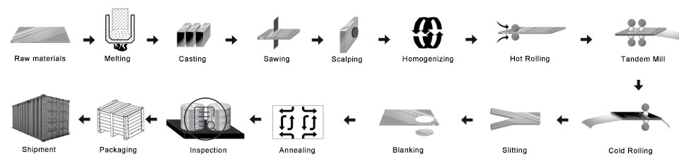
Processo de Círculos de Alumínio
Lingotes/Ligas Mestres — Forno de fusão – Forno de retenção — DC. Rodízio — Laje —- Escalpador — Laminador a Quente – Laminador a Frio – Puncionamento – Forno de Recozimento — Inspeção Final – Embalagem — Entrega
- Prepare as ligas mestres
- Forno de fusão: coloque as ligas no forno de fusão
- Lingote de alumínio fundido DC: Para fazer o lingote mãe
- Fresar o lingote de alumínio: para tornar a superfície e o lado lisos
- Forno de aquecimento
- Laminador a quente: fez a bobina mãe
- Laminador a frio: a bobina mãe foi enrolada conforme a espessura que você deseja comprar
- Processo de perfuração: torne-se do tamanho que você deseja
- Forno de recozimento: mudar o temperamento
- Inspeção final
- Embalagem: caixa de madeira ou palete de madeira
- Entrega
Controle de qualidade
Garantia Abaixo a inspeção será feita na produção.
- um. detecção de raios—TR;
- b. testes ultrassônicos—UT;
- c. Teste de Partículas Magnéticas-MT;
- d. testes de penetração-PT;
- e. detecção de falhas por correntes parasitas-ET
1) Esteja livre de manchas de óleo, Dente, Inclusão, Arranhões, Mancha, Descoloração Óxida, Pausas, Corrosão, Marcas de rolo, Listras de sujeira, e outros defeitos que interferirão no uso.
2) Superfície sem linha preta, limpo, mancha periódica, defeitos de impressão em rolo, como outros padrões de controle interno da gko.
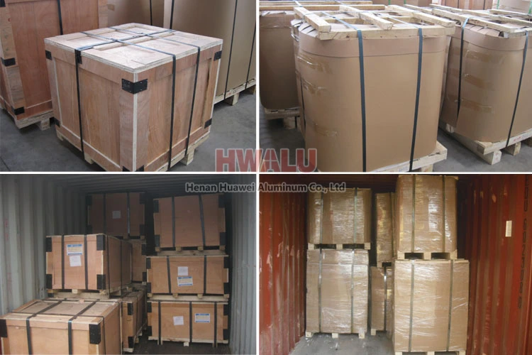
Embalagem de discos de alumínio:
Os círculos de alumínio podem ser embalados de acordo com os padrões de exportação, cobrindo com papel pardo e filme plástico. Finalmente, a Rodada de Alumínio é fixada em um palete de madeira/caixa de madeira.
- Coloque os secadores ao lado do círculo de alumínio, mantenha os produtos secos e limpos.
- Use papel plástico limpo, embale o círculo de alumínio, mantenha uma boa vedação.
- Use o papel de pele de cobra, embale a superfície do papel plástico, mantenha uma boa vedação.
- Próximo, existem duas formas de embalagem: Uma maneira é a embalagem de paletes de madeira, usando o papel crocante embalando a superfície; Outra forma é a embalagem em caixa de madeira, usando a caixa de madeira embalando a superfície.
- Finalmente, coloque a correia de aço na superfície da caixa de madeira, mantendo a solidez e segurança da caixa de madeira.
Círculo de alumínio de Henan Huawei Alumínio. atender ao padrão de exportação. Filme plástico e papel pardo podem ser cobertos de acordo com as necessidades dos clientes. Além do mais, uma caixa de madeira ou palete de madeira é adotada para proteger os produtos contra danos durante a entrega. Existem dois tipos de embalagens, que estão de olho na parede ou de olho no céu. Os clientes podem escolher qualquer um deles para sua conveniência. De um modo geral, há 2 toneladas em um pacote, e carregando 18-22 toneladas em contêiner 1×20′, e 20-24 toneladas em contêiner 1×40′.
Por que nos escolher?
Para acompanhar os tempos, A HWALU continua introduzindo equipamentos e técnicas de última geração para melhorar sua competitividade. Sempre siga a filosofia empresarial de qualidade como centro e cliente em primeiro lugar, fornecer produtos da série de círculo de disco de alumínio da mais alta qualidade para todas as partes do mundo. Mais …