Aluminum Disc Stamping and Drawing Processing: Analysis of Main Causes for Cracking and Wrinkling of Aluminum Discs for Kitchenware
Aluminum disc stamping and drawing processing is the core technology for aluminum-disc-stamping-and-stretching for kitchenware (base materials for woks and soup pots) into cavity structures. However, frequent “cracking” and “wrinkling” defects during processing reduce the finished product qualification rate to only 75%-85%, significantly increasing production costs. Focusing on the principle of aluminum disc stamping and drawing processing, this paper systematically analyzes the causes of defects by combining aluminum alloy material properties, process parameter control, and mold design requirements: Cracking stems from insufficient material adaptability, unbalanced process parameters, mold stress concentration, and lack of pretreatment during processing; Wrinkling is directly related to ineffective blank holder force constraint, mismatched drawing ratio, material geometric deviation, and mold positioning error during processing. The paper reveals the interactive effects of various factors through quantitative experimental data (e.g., defect rate changes under different processing parameters) and proposes targeted optimization schemes for aluminum disc stamping and drawing processing, providing technical support for improving process stability.

1. Introduction
As a cold plastic deformation process, aluminum disc stamping and drawing processing plays a key role in transforming aluminum discs for kitchenware (2.0-4.0mm thick) into cavity structures. For example, to produce a wok with a diameter of 30cm, this process is required to stretch the aluminum disc into an arc-shaped cavity with a depth of 12-15mm; to produce a flat pan, stamping is needed to achieve edge folding and bottom flattening. Currently, this process accounts for over 80% of the total processing volume of aluminum discs for kitchenware and serves as the core link for mass production of mid-to-low-end aluminum alloy kitchenware.
However, “cracking” (mostly occurring at the fillet of the cavity bottom and the middle of the sidewall) and “wrinkling” (concentrated at the edge transition area and local sidewall) defects are prominent in aluminum disc stamping and drawing processing. Industry data shows that the cracking rate of ordinary production lines is 8%-12% and the wrinkling rate is 5%-8%. The combination of these two defects leads to a semi-finished product scrap rate of over 15%, with a daily loss of more than 20,000 RMB per production line. Currently, the industry mostly relies on empirical adjustments (e.g., manual fine-tuning of process parameters) to handle defects, lacking systematic analysis of the essence of aluminum disc stamping and drawing processing. Therefore, in-depth exploration of the core causes of defects under this process is crucial for optimizing the processing flow and reducing costs.
2. Characteristics and Defect Manifestations of Aluminum Disc Stamping and Drawing Processing
2.1 Core Process Characteristics
Aluminum disc stamping and drawing processing must meet two core requirements: “forming integrity” and “mechanical stability”. The former requires no cracks or wrinkles in the cavity after processing, with a dimensional tolerance of ≤±0.5mm; the latter requires no excessive hardening of the aluminum substrate after processing (to avoid deformation during subsequent use). During processing, aluminum discs for kitchenware are subjected to combined stresses of “blank holder force (restricting edge flow) – drawing force (driving material into the mold cavity) – friction force (generated by material-mold contact)”. The uniformity of stress distribution directly determines whether defects occur – this is the core feature that distinguishes aluminum disc stamping and drawing processing from other aluminum processing technologies.
2.2 Typical Defect Manifestations
- Cracking Defects: Classified by location in aluminum disc stamping and drawing processing, they include “bottom cracking” (at mold fillets, with crack lengths of 1-5mm, mostly penetrating) and “sidewall cracking” (in the middle of the sidewall or transition area, longitudinal non-penetrating). Classified by cause, they include “brittle cracking” (excessive material hardness during processing, with flat crack edges) and “plastic cracking” (processing stress exceeding material tensile strength, with tensile deformation at crack edges).
- Wrinkling Defects: Classified by morphology in aluminum disc stamping and drawing processing, they include “edge wrinkling” (aluminum disc edges not constrained by the blank holder, forming annular wrinkles with a height of 0.3-1mm) and “sidewall wrinkling” (material accumulation on the sidewall, forming longitudinal or diagonal wrinkles that affect coating adhesion). Classified by cause, they include “compression wrinkling” (transverse material compression exceeding the consumption capacity of drawing during processing) and “shear wrinkling” (uneven material flow rate causing local shear stress during processing).

3. Main Causes of Cracking in Aluminum Disc Stamping and Drawing Processing
3.1 Insufficient Material Adaptability: Mismatch Between Processing and Grade Characteristics
Aluminum disc stamping and drawing processing has strict requirements for material performance. The differences in processing adaptability of common grades of aluminum discs for kitchenware (1050 pure aluminum, 3003 aluminum-manganese alloy) directly affect the cracking risk, with specific parameters shown in Table 1:
Table 1 Performance and Adaptability Comparison of Common Grades of Aluminum Discs for Kitchenware in Aluminum Disc Stamping and Drawing Processing
| Aluminum Alloy Grade |
Purity (%) |
Tensile Strength (MPa) |
Elongation (%) |
Suitable Processing Scenarios for Aluminum Disc Stamping and Drawing |
Processing Scenarios Prone to Cracking |
| 1050 (Pure Aluminum) |
≥99.5 |
≥75 |
≥35 |
Shallow drawing (depth ≤5mm, e.g., flat pans) |
Deep drawing (e.g., woks), drawing ratio >1:1.5 |
| 3003 (Al-Mn Alloy) |
≥99.0 |
≥110 |
≥20 |
Deep drawing (depth 5-15mm, e.g., woks) |
Blank holder force >0.6MPa, insufficient annealing |
- Incorrect Grade Selection: In aluminum disc stamping and drawing processing, 1050 pure aluminum has low tensile strength and is only suitable for shallow drawing. If used for deep drawing of woks, the sidewall is prone to cracking because the drawing stress exceeds the material’s load capacity. Although 3003 aluminum-manganese alloy is suitable for deep drawing, excessive blank holder force during processing causes edge hardening, leading to cracking in the transition area.
- Material Purity Defects: If aluminum discs for kitchenware contain excessive impurities (Al₂O₃, SiO₂ >0.5% or Fe, Cu >0.3%), these impurities become “stress concentration points” during processing. For example, the Al₃Fe compound (Vickers hardness (HV) 150) formed by Fe and Al is much harder than the aluminum substrate (HV 30). During stamping and drawing, microcracks easily form around impurities and further expand into macro cracks. Experiments show that when impurity content increases from 0.2% to 0.8%, the cracking rate in aluminum disc stamping and drawing processing rises from 5% to 18%.
3.2 Unbalanced Process Parameters: Out-of-Control Stress Distribution During Processing
The coordination of core parameters (drawing speed, blank holder force, drawing ratio) in aluminum disc stamping and drawing processing directly affects stress distribution, and parameter imbalance is the main cause of cracking:
- Excessively High Drawing Speed: The reasonable drawing speed range for aluminum disc stamping and drawing processing is 50-80mm/s (based on 1050/3003 grades). If the speed exceeds 100mm/s, material deformation cannot be transmitted evenly, and local areas such as mold fillets are prone to cracking due to “instantaneous stress peaks” (2-3 times higher than the material’s yield strength). For example, when a factory processed 3003 aluminum discs (3mm thick) and increased the speed from 70mm/s to 120mm/s, the sidewall cracking rate rose from 8% to 25%.
- Unreasonable Blank Holder Force: During processing, the blank holder force must balance “constraining edges” and “avoiding crushing”, with a reasonable range of 0.3-0.5MPa (for aluminum discs with a diameter of 20-35cm). Insufficient blank holder force causes excessive edge flow, leading to sidewall thinning (deviation >20%) and local stress concentration cracking. When the blank holder force exceeds 0.6MPa, the material edges harden (HV increases from 35 to 50) and ductility decreases, resulting in cracking in the transition area during drawing.
- Excessively Large Drawing Ratio: In aluminum disc stamping and drawing processing, the drawing ratio (aluminum disc diameter / opening diameter of the processed workpiece) must match the material elongation – the maximum drawing ratio is 1:1.5 for 1050 pure aluminum and 1:1.8 for 3003 aluminum-manganese alloy. If the drawing ratio exceeds the limit (e.g., 3003 alloy used for 1:2.0 processing), the sidewall thinning rate exceeds 30%, and cracking easily occurs due to “insufficient thickness – stress overload”.
3.3 Mold Design Defects: Abnormal Stress Transmission During Processing
Molds are the stress transmission carriers in aluminum disc stamping and drawing processing, and design defects directly induce cracking:
- Excessively Small Fillet Radius: The fillets at the mold bottom and sidewall transition are stress concentration areas during processing. The reasonable radius should be 3-5 times the thickness of the aluminum disc (e.g., ≥7.5mm for 2.5mm thick aluminum discs). If the radius is <5mm (e.g., 3mm), the bending stress increases sharply when the material flows through (stress concentration factor rises from 1.2 to 2.5), increasing the risk of bottom cracking. Simulation experiments show that when the fillet radius decreases from 8mm to 4mm, the bottom cracking rate during processing rises from 4% to 16%.
- Uneven Clearance and Excessive Roughness: The reasonable clearance between the mold punch and die is 1.05-1.1 times the thickness of the aluminum disc (e.g., 2.1-2.2mm for 2mm thick discs). If the clearance is uneven (e.g., 2.0mm on one side and 2.4mm on the other), the deformation difference between the two sides of the material exceeds 15% during processing, and the thinner side is prone to cracking due to excessive drawing. When the mold surface roughness Ra >1.6μm, the friction coefficient increases from 0.15 to 0.3, causing uneven material flow resistance and sidewall cracking due to “drag stress”.
3.4 Lack of Pretreatment: Substandard Material Condition Before Processing
Pretreatment before aluminum disc stamping and drawing processing directly affects forming performance. The pretreatment processes and processing adaptability of different grades are shown in Table 2:
Table 2 Annealing Process Parameters and Forming Performance of Aluminum Discs Before Stamping and Drawing Processing
| Aluminum Alloy Grade |
Annealing Temperature (℃) |
Holding Time (h) |
Cooling Method |
Hardness After Annealing (HV) |
Elongation After Annealing (%) |
Cracking Risk If Substandard During Processing |
| 1050 (Pure Aluminum) |
300-320 |
1.0-1.5 |
Air Cooling |
≤35 |
≥35 |
Brittle cracking rate increases by 15% when hardness >40 |
| 3003 (Al-Mn Alloy) |
320-350 |
1.5-2.0 |
Air Cooling |
≤45 |
≥20 |
Plastic cracking rate increases by 12% when elongation <18% |
- Insufficient Annealing: Aluminum discs have “work hardening” after rolling, and annealing is required to eliminate internal stress. If 1050 pure aluminum is only annealed at 250℃ for 0.5h, the material hardness rises to HV 45 during processing, making it prone to brittle cracking. If the holding time for 3003 aluminum-manganese alloy is less than 1h, the elongation drops below 18%, leading to sidewall cracking due to insufficient plasticity during processing.
- Surface Contamination: Residual rolling oil (>5mg/m²) or dust (>1μm) on the aluminum disc surface forms an “isolation layer” during processing. Rolling oil reduces the friction coefficient, causing local material flow to be too fast and sidewall thinning cracking; dust forms indentations on the material surface, becoming the starting point of cracking.

4. Main Causes of Wrinkling in Aluminum Disc Stamping and Drawing Processing
4.1 Ineffective Blank Holder Force Constraint: Out-of-Control Edge Flow During Processing
Blank holder force is the core parameter for suppressing edge wrinkling in aluminum disc stamping and drawing processing, and ineffective constraint directly induces defects:
- Blank Holder Force Below Critical Value: During processing, the edges of the aluminum disc produce “transverse compressive deformation” due to “radial drawing stress”. If the blank holder force does not reach the critical value (calculation formula: F=k×t×D, where k is the material coefficient, t is thickness, and D is diameter), edge material accumulates to form annular wrinkles. For example, the critical blank holder force for 3003 aluminum discs (2.5mm thick, 30cm diameter) is 0.35MPa; when the blank holder force decreases to 0.2MPa, the edge wrinkling rate during processing rises from 3% to 22%.
- Concentricity Deviation of Blank Holder: If the concentricity deviation between the blank holder and the die exceeds 0.1mm, local blank holder force is insufficient during processing (e.g., 0.2MPa on one side and 0.4MPa on the other). Material in the insufficient area flows excessively, forming “local edge wrinkling”, with the wrinkle direction consistent with the deviation direction.
4.2 Mismatched Drawing Ratio: Excessive Material Surplus During Processing
A too-small drawing ratio in aluminum disc stamping and drawing processing means “excessive difference between the aluminum disc area and the processed workpiece surface area”. The surplus material cannot be consumed through deformation, leading to wrinkling:
- Too-Small Diameter Ratio: For example, when producing a wok with a diameter of 25cm, if an aluminum disc with a diameter of 28cm is used (diameter ratio 1:1.12), which is much lower than the reasonable diameter ratio (1:1.8) for 3003 alloy processing, the surplus material forms longitudinal wrinkles on the sidewall. Experiments show that when the diameter ratio decreases from 1:1.8 to 1:1.2, the sidewall wrinkling rate during processing rises from 4% to 19%.
- Local Drawing Ratio Imbalance Caused by Uneven Thickness: If the thickness deviation of the aluminum disc exceeds ±5% (e.g., standard 2mm, actual 1.8mm/2.2mm), the drawing ratio increases in the thin area (material fully deformed) and decreases in the thick area (material insufficiently deformed) during processing. The thick area forms “accumulation wrinkling”.
4.3 Mold Positioning Error: Unbalanced Material Stress During Processing
The mold positioning accuracy in aluminum disc stamping and drawing processing directly affects the uniformity of material stress. The relationship between positioning deviation and wrinkling rate is shown in Table 3:
Table 3 Effect of Mold Locating Pin Deviation on Wrinkling Rate of 3003 Aluminum Discs (2.5mm Thick, 30cm Diameter) in Stamping and Drawing Processing
| Locating Pin Deviation (mm) |
Concentricity Between Aluminum Disc and Mold |
Wrinkling Rate During Processing (%) |
Wrinkling Position |
Defect Manifestation |
| ≤0.05 |
Good (deviation <0.1mm) |
≤3 |
No obvious wrinkling |
Flat cavity surface, no edge accumulation |
| 0.1-0.2 |
Moderate (deviation 0.1-0.2mm) |
8-12 |
Unilateral edge |
Local annular wrinkles, height ≤0.5mm |
| 0.2-0.3 |
Poor (deviation 0.2-0.3mm) |
20-25 |
Unilateral sidewall + edge |
Longitudinal sidewall wrinkles, obvious edge accumulation |
| >0.3 |
Very Poor (deviation >0.3mm) |
>30 |
Bilateral sidewall + edge |
Large-area wrinkles, unable to process further |
- Locating Pin Deviation: If the locating pin deviation exceeds 0.2mm during processing, the center of the aluminum disc is not coaxial with the mold center. Material on one side is over-drawn (high stress) and compressed on the other side (low stress), causing wrinkling on the compressed side. For example, when the locating pin of a production line deviated by 0.3mm, the unilateral wrinkling rate during processing reached 30%.
- Guide Bushing Wear: Wear of the guide bushing causes uneven clearance between the punch and die (e.g., 2.1mm on one side and 2.3mm on the other). During processing, material flows faster in the area with larger clearance and slower in the area with smaller clearance, leading to material accumulation and wrinkling on the slower side.
5. Interactive Effects of Cracking and Wrinkling in Aluminum Disc Stamping and Drawing Processing
Cracking and wrinkling are not independent in aluminum disc stamping and drawing processing but exhibit interactive effects of “stress imbalance transfer”. Specific quantitative data are shown in Table 4:
Table 4 Cracking and Wrinkling Rates of 3003 Aluminum Discs (2.5mm Thick, 30cm Diameter) Under Different Blank Holder Forces in Stamping and Drawing Processing
| Blank Holder Force (MPa) |
Drawing Speed (mm/s) |
Cracking Rate During Processing (%) |
Wrinkling Rate During Processing (%) |
Main Defect Type |
Cause Analysis |
| 0.2 |
70 |
5 |
22 |
Edge wrinkling mainly |
Insufficient blank holder force, edge material accumulation |
| 0.35 |
70 |
8 |
3 |
No obvious defects |
Reasonable blank holder force, uniform material flow |
| 0.5 |
70 |
18 |
2 |
Sidewall cracking mainly |
Excessive blank holder force, increased material hardness |
| 0.35 |
100 |
25 |
4 |
Bottom cracking mainly |
Excessively high drawing speed, local stress overload |
| 0.35 |
40 |
6 |
15 |
Sidewall wrinkling mainly |
Excessively low drawing speed, uneven material flow |
As shown in Table 4, in aluminum disc stamping and drawing processing, the defect rate is the lowest (total defect rate 11%) when the blank holder force is 0.35MPa and the drawing speed is 70mm/s. When the blank holder force deviates from the reasonable range or the speed is abnormal, the cracking and wrinkling rates show “reverse changes” – insufficient blank holder force increases the wrinkling rate and decreases the cracking rate, while excessive blank holder force increases the cracking rate and decreases the wrinkling rate. This essentially reflects the transfer of stress distribution imbalance during processing.
6. Optimization Strategies for Aluminum Disc Stamping and Drawing Processing
6.1 Material and Pretreatment Optimization
- Precise Material Selection: In aluminum disc stamping and drawing processing, 1050 pure aluminum is selected for shallow drawing (flat pans, depth ≤5mm), and 3003 aluminum-manganese alloy is selected for deep drawing (woks, depth 10-15mm). The material should have impurity content ≤0.2% and thickness deviation ≤±3%.
- Standardized Pretreatment: Refer to the process in Table 2 – 1050 pure aluminum is annealed at 300-320℃ for 1.2h with air cooling, and 3003 aluminum-manganese alloy is annealed at 330-350℃ for 1.8h with air cooling. “Alkali cleaning (2% NaOH, 50℃, 30s) + water cleaning + hot air drying” is used to ensure surface oil content ≤1mg/m² and dust ≤0.5μm.
6.2 Coordinated Regulation of Process Parameters
- Drawing Speed: Control the processing speed at 60-70mm/s for 1050 pure aluminum and 50-60mm/s for 3003 aluminum-manganese alloy, with a speed fluctuation of ≤±5mm/s.
- Blank Holder Force Calculation: Calculate using the formula F=0.35×t×D (t = thickness, D = diameter, unit: mm). For example, the blank holder force for 3003 aluminum discs (2.5mm thick, 30cm diameter) is 0.35×2.5×300=262.5N (approximately 0.36MPa), with an actual adjustment range of ±0.02MPa.
- Drawing Ratio Control: The diameter ratio for 1050 pure aluminum processing is ≤1:1.5, and for 3003 aluminum-manganese alloy is ≤1:1.8. The thickness ratio (minimum thickness after processing / original thickness) is ≥0.7 to avoid excessive drawing.
6.3 Mold Structure Improvement
- Fillet and Clearance Design: The bottom fillet radius = 4×t (t = aluminum disc thickness), and the sidewall transition fillet radius = 3×t (e.g., 10mm bottom fillet and 7.5mm transition fillet for 2.5mm thick aluminum discs). The punch-die clearance = 1.08×t (±0.02mm).
- Positioning and Surface Treatment: Refer to the requirements in Table 3 – the concentricity deviation between the locating pin and the mold is ≤0.05mm, and the guide bushing wear is ≤0.03mm (inspect and replace worn parts every 5,000 workpieces processed). The mold working surface roughness Ra ≤0.6μm, with a roughness difference of ≤0.2μm between different areas.

7. Conclusion
In aluminum disc stamping and drawing processing, the cracking and wrinkling of aluminum discs for kitchenware are the result of the combined action of “material adaptability – process parameters – mold design – pretreatment”. The core causes of cracking are incorrect material selection, unbalanced parameters, mold stress concentration, and lack of pretreatment during processing; the core causes of wrinkling are ineffective blank holder force constraint, mismatched drawing ratio, and mold positioning deviation during processing. The two defects interact through “stress imbalance transfer”, further increasing the defect risk.
Through targeted optimization – ensuring processing adaptability on the material side, achieving parameter coordination on the process side, improving positioning and geometric accuracy on the mold side, and standardizing annealing and cleaning on the pretreatment side – the cracking rate in aluminum disc stamping and drawing processing can be reduced to below 5%, the wrinkling rate to below 3%, and the total defect rate to within 8%. In the future, combining AI visual inspection (real-time defect identification during processing) and finite element simulation (predicting processing stress distribution) can further improve process control accuracy and promote the intelligent development of aluminum disc stamping and drawing processing.
Properties of the aluminum circle:
Aluminum circle is suitable for many markets, including cookware, automotive and lighting industries, etc., thanks to good product characteristics:
- Low anisotropy, which facilitates deep drawing
- Strong mechanical properties
- High and homogeneous heat diffusion
- Ability to be enameled, covered by PTFE (or others), anodized
- Good reflectivity
- High strength-to-weight ratio
- Durability and resistance to corrosion
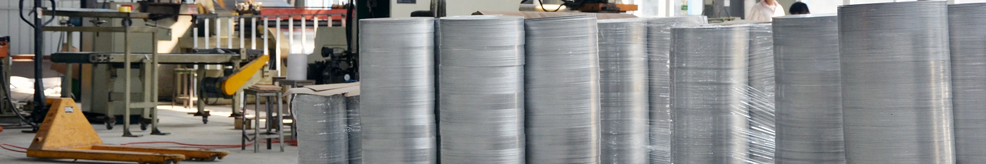
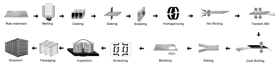
Aluminum Circles Process
Ingot/Master Alloys — Melting Furnace – Holding Furnace — D.C. Caster — Slab —- Scalper — Hot Rolling Mill – Cold Rolling Mill – Punching – Annealing Furnace — Final Inspection – Packing — Delivery
- Prepare the master alloys
- Melting furnace: put the alloys into the melting furnace
- D.C.cast aluminum ingot: To make the mother ingot
- Mill the aluminum ingot: to make the surface and side smooth
- Heating furnace
- Hot rolling mill: made the mother coil
- Colding rolling mill: the mother coil was rolled as the thickness you want to buy
- Punching process: become the size what you want
- Annealing furnace: change the temper
- Final inspection
- Packing: wooden case or wooden pallet
- Delivery
Quality Control
Assurance Below inspection will be done in the production.
- a. ray detection—RT;
- b. ultrasonic testing—UT;
- c. Magnetic Particle Testing-MT;
- d. penetration testing-PT;
- e. eddy current flaw detection-ET
1) Be free from Oil Stain, Dent, Inclusion, Scratches, Stain, Oxide Discoloration, Breaks, Corrosion, Roll Marks, Dirt Streaks, and other defects which will interfere with use.
2) Surface without black line, clean-cut, periodic stain, roller printing defects, such as other gko internal Control standards.
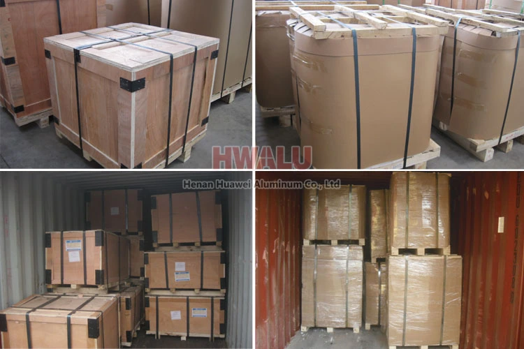
Aluminum discs packing:
Aluminum circles can be packed by export standards, covering with brown paper and plastic film. Finally, the Aluminium Round is fixed on a wooden pallet/wooden case.
- Put the driers side the aluminum circle, keep the products dry and clean.
- Use clean plastic paper, pack the aluminium circle, keep good sealing.
- Use the snakeskin paper, pack the surface of the plastic paper, keep good sealing.
- Next, there are two ways of packaging: One way is wooden pallet packaging, using the crusty paper packing the surface; Another way is wooden case packaging, using the wooden case packing the surface.
- Finally, lay the steel belt on the wooden box’s surface, keeping the wooden box fastness and secure.
Aluminum circle of Henan Huawei Aluminum. meet the export standard. Plastic film and brown paper can be covered at customers’ needs. What’s more, a wooden case or wooden pallet is adopted to protect products from damage during delivery. There are two kinds of packaging, which are eye to wall or eye to the sky. Customers can choose either of them for their convenience. Generally speaking, there are 2 tons in one package, and loading 18-22 tons in 1×20′ container, and 20-24 tons in 1×40′ container.
Why choose us?
In order to move with the times, HWALU keeps introducing the state of the art equipment and technique to improve its competitiveness. Always adhere to the business philosophy of quality as the center and customer first, to provide the highest quality aluminum disc circle series products to all parts of the world. More …