Comprehensive Guide to Burr Removal and Surface Finish Control for 1050 Stamped Aluminum Discs
I. Introduction: The Paradox of Purity and Processability
1050 aluminum alloy stands as the quintessential representative of high-purity industrial aluminum, boasting an aluminum content of no less than 99.5%. Its chemical simplicity—devoid of significant alloying elements like magnesium, silicon, or manganese—bestows upon it a unique set of physical properties that are both a blessing and a challenge in manufacturing.
Characterized by exceptional electrical and thermal conductivity, superior corrosion resistance, and remarkable workability, 1050 is the material of choice for applications ranging from cookware and lighting reflectors to electronic heat sinks and decorative hardware.
However, its most defining trait—extreme plasticity—is also the root cause of its primary manufacturing pitfall: burr formation.
In high-speed stamping operations, 1050 aluminum’s low tensile strength (105-145 MPa) and high elongation mean it behaves less like a brittle solid and more like a viscous fluid. Instead of fracturing cleanly, the material tends to stretch, tear, and adhere to tooling.
This results in fibrous burrs, micro-scratches, and die buildup, which degrade dimensional accuracy and surface quality. These defects propagate downstream, causing cracks during deep drawing, uneven anodizing, and compromised aesthetics.
This guide provides a systematic framework for mastering 1050 aluminum disc production. We move beyond isolated fixes to present an integrated approach covering material science, tooling design, process optimization, and post-processing. Our goal is to transform the inherent softness of 1050 from a liability into a hallmark of high-quality, high-precision manufacturing.
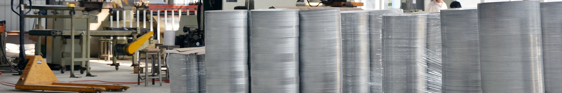
 aluminum-stamping-parts-1
1.1 Material Benchmarking: Why 1050 is Unique
To select the right process, one must first understand how 1050 differs from its common counterparts. The following comparative analysis highlights why 1050 cannot be treated like a standard alloy.
| Alloy Grade |
Key Characteristics |
Hardness & Plasticity |
Stamping & Burr Profile |
Deburring Difficulty |
Surface Finish Potential |
| 1050 |
High Purity (≥99.5%) |
Very Soft / Highly Ductile |
Fibrous, stringy burrs; high die-sticking risk. |
Moderate (Requires gentle handling) |
Excellent (Ideal for mirror finishes) |
| 1060 |
Higher Purity (≥99.6%) |
Softer than 1050 |
Similar to 1050, but more prone to galling. |
Moderate |
Excellent |
| 3003 |
Al-Mn Alloy |
Medium Strength |
Brittle shear burrs; clean break; low sticking. |
Easy |
Good (But less lustrous) |
| 5052 |
Al-Mg Alloy |
High Strength |
Hard, chunky burrs; prone to cracking. |
Hard |
Fair (Struggles with high gloss) |
Conclusion: 1050’s high purity grants it superior surface aesthetics but demands a specialized “soft-touch” manufacturing regimen. Aggressive tooling or harsh deburring will ruin the workpiece.
II. Root Cause Analysis: Deconstructing Burr Formation
Effective control begins with understanding the causality of defects. In 1050 stamping, burrs are a symptom of a multi-variable system.
2.1 Material Intrinsic Factors
The low yield strength of 1050 means the material undergoes significant plastic deformation before separation. During the shearing phase, the aluminum is pulled and stretched rather than cleanly cut. This “drawing” action creates long, thin filaments of metal (stringers). Furthermore, aluminum’s natural affinity for iron causes microscopic welding to the die surface, leading to built-up edge (BUE) that acts as a secondary, irregular cutting tool, exacerbating burr height and surface roughness.
2.2 Tooling Geometry and Maintenance
The die is the heart of the operation.
- Clearance: The gap between punch and die is critical. For 1050, the optimal clearance is typically 5% to 8% of the material thickness. Clearance that is too large causes excessive plastic deformation and rollover, creating heavy burrs. Clearance that is too small causes secondary cutting and accelerated tool wear.
- Edge Condition: A sharp die edge minimizes the force required for initiation. A worn or rounded edge increases the burnishing distance, generating more heat and larger burrs.
- Surface Treatment: Uncoated steel dies readily gall with aluminum. Modern production requires dies treated with DLC (Diamond-Like Carbon) or TiAlN (Titanium Aluminum Nitride) coatings to reduce friction and prevent adhesion.
2.3 Process Dynamics
- Stamping Velocity: High speeds generate heat and shock, which can soften the aluminum locally and increase sticking. Controlled speeds allow for smoother fracture propagation.
- Blank Holding Force: Insufficient force allows the sheet to wrinkle or shift, causing uneven shearing. Excessive force induces marring and increases the risk of die pickup.
2.4 Lubrication Failure
Water-based or low-viscosity oils fail to create a robust hydrodynamic film between the soft aluminum and the hard die. This leads to metal-to-metal contact, welding, and catastrophic surface damage. 1050 requires high-performance, high-extreme-pressure (EP) lubricants specifically formulated for soft alloys.
III. Source Prevention: Optimizing the Stamping Process
The most cost-effective burr is the one never created. Front-end optimization reduces the burden on downstream finishing.
3.1 Precision Tooling Strategy
Investing in tooling pays dividends.
- Clearance Setting: Maintain the 5-8% sweet spot. Use shims to ensure parallelism.
- Coating Technology: Utilize DLC-coated punches. The low surface energy of DLC prevents aluminum from sticking, ensuring a clean release with every stroke.
- Regular Maintenance: Implement a preventative maintenance schedule. Polish die edges and inspect for micro-chipping every 50,000 strokes.
3.2 Advanced Lubrication Management
- Chemistry: Use synthetic ester-based stamping fluids. These provide a strong boundary lubrication layer that prevents microwelding even under high pressure.
- Application: Ensure full flood lubrication or misting. Spot dryness is the enemy of consistency.
3.3 Raw Material State Selection
1050 is available in various tempers, each suited for different forming challenges. Selecting the correct temper is a primary control lever.
| Temper State |
Mechanical Properties |
Formability & Burr Tendency |
Ideal Application |
| O (Annealed) |
Softest, Highest Ductility |
Easiest to draw; highest burr/fiber generation. |
Deep-drawn cookware, complex shapes. |
| H12 / H14 |
Strain-Hardened (1/4, 1/2 Hard) |
Good balance; reduced sticking vs. O-temper. |
General stamping, medium-depth draws. |
| H24 |
Partially Annealed |
Highest stiffness; cleanest cut, least burrs. |
Flat blanks, shallow stampings. |
Recommendation: For deep-drawn kitchen sinks or lampshades, use O-temper. For precision flat discs or electronic shields, use H14 or H24 to minimize edge defects.
IV. Deburring Technologies: A Comparative Analysis
Despite best efforts, some micro-burrs are inevitable. The choice of removal method depends on the geometry, volume, and required surface quality.
| Process |
Mechanism |
Pros |
Cons |
Best Suited For |
| Vibratory Finishing |
Media abrasion via vibration. |
Low cost; high volume; gentle. |
Slow; ineffective on heavy burrs. |
General industrial discs; pre-anodizing prep. |
| Centrifugal Barrel |
High-energy media impact. |
Fast; aggressive; good edge radius. |
High media wear; noise. |
Removing heavy stamping burrs. |
| Thermal Deburring |
Rapid gas combustion. |
Removes internal/external burrs. |
Expensive; alters surface chemistry. |
Complex geometries, internal holes. |
| Electrochemical (ECM) |
Controlled anodic dissolution. |
Stress-free; mirror finish possible. |
Requires conductive fixtures; waste treatment. |
Medical, electronics, high-precision parts. |
| Manual/Brush |
Mechanical scrubbing. |
Flexible; precise. |
Labor-intensive; inconsistent. |
Large diameters (>500mm); prototypes. |
4.1 Vibratory Finishing: The Workhorse
For most 1050 disc applications, vibratory finishing is the standard. The key is selecting the right media. Do not use hard ceramics on soft aluminum, as they will cause impingement and surface pitting. Use high-density alumina cones or resin-bonded media with a mild acidic compound to clean and brighten the surface simultaneously. Cycle times typically range from 30 to 90 minutes depending on burr size.
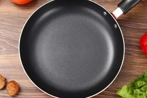
 Aluminum sheet manufacturing factory
4.2 Electrochemical Deburring (ECD): The Precision Solution
When tolerances are tight (e.g., electronic heat sinks), ECD is superior. An electrolytic cell is created where the aluminum part is the anode. A precisely shaped cathode is brought close to the burr. The electric current preferentially dissolves the burr tip, which has the highest current density. This leaves a perfectly smooth edge with no mechanical stress, preventing distortion in thin-walled parts.
V. Surface Finish Enhancement: Beyond Burr Removal
A part can be burr-free but still visually unacceptable due to roller marks, die scratches, or oxidation. 1050’s high purity makes it an excellent candidate for high-luster finishes.
5.1 Chemical Polishing and Brightening
To achieve a uniform, reflective surface, chemical polishing is employed. The parts are immersed in a phosphoric-nitric acid bath at controlled temperatures (90-110°C). The acid attacks the high points of the surface topography, leveling the micro-peaks and valleys. This process can achieve a reflectivity of over 85%, transforming a standard stamped disc into a high-end lighting reflector.
5.2 Electro-Polishing
For the ultimate finish, electropolishing is used. Similar to ECM, it removes a thin, controlled layer of material electrochemically. Unlike mechanical polishing, which can smear the metal surface and trap contaminants, electropolishing creates a passive, chromium-rich layer (if applicable) or a pure aluminum oxide layer that is highly corrosion-resistant and brilliantly shiny.
5.3 Cleaning and Passivation
Post-machining contaminants (oils, polishing compounds) must be removed to prevent staining.
- Degreasing: Use an alkaline cleaner to emulsify oils.
- Acid Pickling: A mild nitric acid dip removes smut and oxides.
- Drying: Use forced hot air drying. Air drying leads to water spots, which are a common rejection reason for 1050 parts.
VI. Quality Assurance and Metrology
Subjective visual inspection is insufficient. A robust quality system requires quantifiable metrics.
6.1 Burr Height Measurement
- Standard: ISO 9013 (for thermal cutting) or internal standards.
- Tools: Digital height gauges, optical comparators, or laser scanning microscopes.
- Acceptance: For general parts, burr height should be < 0.05mm. For precision assemblies, < 0.01mm.
6.2 Surface Roughness (Ra/Rz)
- Tools: Portable stylus profilometers.
- Targets:
- As-Stamped: Ra 0.8 – 1.6 μm
- Deburred: Ra 0.4 – 0.8 μm
- Polished: Ra 0.1 – 0.4 μm
- Mirror: Ra < 0.05 μm
6.3 Visual Standards
Establish master samples for acceptable surface appearance. Define what constitutes a “scratch” versus a “flow line.” Use standardized light boxes (D65 light source) for color and gloss consistency.
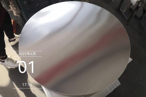
 Aluminum circular sheet
VII. Conclusion: The Integrated Manufacturing System
Controlling burrs and finish in 1050 aluminum is not about finding a magic bullet; it is about implementing a systematic cascade of controls:
- Design: Select the right temper and specify realistic tolerances.
- Tooling: Invest in coated, precision-ground dies with correct clearance.
- Process: Use proper lubrication and controlled parameters.
- Finish: Apply the appropriate deburring and polishing technology.
- Verify: Measure and document results.
By respecting the material’s unique properties and managing the entire process chain, manufacturers can reliably produce 1050 aluminum discs that meet the most demanding aesthetic and functional requirements, turning a potentially problematic material into a premium product.