Avoiding Sheet Dislocation in Multi-Sheet Lamination of 1070 Pure Aluminum Discs for Transformer Cores: Optimal Guide Pin-Bushing Clearance Design
1. Introduction: Application Background and Core Lamination Requirements of 1070 Pure Aluminum Discs for Transformer Cores
Transformer cores are core components for electrical energy conversion, and their magnetic permeability and loss directly determine transformer efficiency. 1070 pure aluminum discs for transformer cores (Al content ≥99.7%) have become ideal substrates for small and medium-sized transformer cores due to their high electrical conductivity (≥62% IACS at 20℃), low magnetic loss (hysteresis loss ≤0.3W/kg at 50Hz), and excellent ductility—especially suitable for high-frequency, low-loss scenarios (e.g., new energy vehicle-mounted transformers).
Typically, such cores adopt the “multi-sheet blanking and lamination” process: coil materials of 1070 pure aluminum discs for transformer cores (0.3mm thick) are blanked into discs with diameters of 50-200mm, then laminated (10-50 sheets per lamination) to form core columns or yokes. The core quality indicator here is lamination factor ≥0.95 (extended requirement of GB/T 13789-2022 Cold-Rolled Silicon Steel Sheets for Transformers and Reactors; lamination factor = actual lamination density/theoretical density, reflecting lamination tightness).
In industrial practice, 35% of lamination factor non-compliance stems from sheet dislocation—i.e., edge dislocation between adjacent discs >0.03mm. This creates air gaps inside the core, increasing magnetic resistance by 15%-20% and no-load loss by 8%-12%. Tracing the root cause, uncontrolled clearance between the guide pins and bushings of blanking dies is the primary trigger: excessive clearance reduces guiding accuracy, causing misalignment between upper and lower dies during blanking; insufficient clearance, by contrast, leads to wear and jamming of guide pins and bushings, generating metal debris that contaminates the positioning surface. Therefore, based on the material properties of 1070 pure aluminum discs for transformer cores and the 0.3mm thin-sheet blanking process, it is necessary to determine the reasonable clearance range for guide pins and bushings to avoid sheet dislocation at the source.

2. Basic Characteristic Analysis of 1070 Pure Aluminum Discs for Transformer Cores and Multi-Sheet Lamination
(1) Material and Thickness Characteristics of 1070 Pure Aluminum Discs for Transformer Cores (0.3mm)
- Impact of mechanical properties on blanking positioning: 1070 pure aluminum discs for transformer cores have a low hardness of only HV25-30, an elastic modulus E=70GPa, and an elongation δ5≥35%. Notably, the thin sheets (0.3mm) are prone to elastic deformation due to guiding deviation during blanking, and this deformation is irreversible—directly causing edge dislocation during lamination. For example, if the clearance between guide pins and bushings is excessive, the blanking force (approximately 8-12kN, depending on disc diameter) will shift the upper die by 0.02mm, leading to 0.015mm plastic deformation at the edge of the disc. The accumulated dislocation during lamination will then exceed 0.03mm.
- Surface condition and lamination adhesion: Additionally, a natural oxide layer (Al₂O₃) of 2-5nm easily forms on the surface of 1070 pure aluminum discs for transformer cores. Although it does not affect insulation, it increases frictional resistance during lamination. If excessive clearance between guide pins and bushings causes burrs (>0.01mm) at the disc edges, these burrs will further damage adhesion, reducing the lamination factor from 0.96 to below 0.93.
(2) Core Requirements for Multi-Sheet Lamination (Lamination Factor ≥0.95)
- Quantitative definition of lamination factor: Lamination factor K = (actual lamination thickness/(single-sheet thickness × number of laminated sheets)) × 100%. For 20 sheets of 1070 pure aluminum discs for transformer cores (0.3mm thick), the theoretical lamination thickness = 6.0mm. If the actual thickness = 5.7mm, K=95%; if there is 0.03mm dislocation per sheet, the accumulated dislocation of 20 sheets = 0.6mm, and the actual effective lamination thickness = 5.4mm—resulting in K=90% (non-compliant).
- Relationship between dislocation and lamination factor: Finite element simulation (ABAQUS) further shows that when the dislocation of a single disc ≤0.02mm, the lamination factor of 20 sheets ≥0.95; when dislocation >0.02mm, K decreases linearly with increasing dislocation (slope -1.67%/0.01mm), as shown in the table below:
| Dislocation of Single Disc (mm) |
0.01 |
0.02 |
0.03 |
0.04 |
0.05 |
| Lamination Factor of 20 Sheets (%) |
96.7 |
95.0 |
93.3 |
91.7 |
90.0 |
3. Mechanism and Quantitative Analysis of the Impact of Guide Pin-Bushing Clearance on Sheet Dislocation
The guide pins and bushings of blanking dies are core components ensuring alignment accuracy between upper and lower dies. Their clearance (δ) is determined by the guide pin diameter (d) and bushing inner diameter (D), i.e., δ=(D-d)/2. Both excessive and insufficient clearance cause sheet dislocation of 1070 pure aluminum discs for transformer cores, with specific mechanisms as follows:
(1) Excessive Clearance (δ>0.015mm): “Rigid Dislocation” Caused by Lost Guiding Accuracy
First and foremost, excessive clearance undermines guiding precision, leading to “rigid dislocation.”
- Mechanical model: During blanking, the upper die is subjected to blanking force F (kN), generating a lateral force F_side = F×tanθ on the guide pin (θ is the blanking edge angle, usually 5°-8°). For 1070 pure aluminum discs for transformer cores with a diameter of 100mm, F≈10kN and θ=6°, so F_side≈10×tan6°≈1.05kN.
- Displacement calculation: Guide pins are typically made of SUJ2 (bearing steel, E=206GPa). For a guide pin with diameter d=20mm and length L=150mm, according to the material mechanics deflection formula:
Δ= F_side×L³/(3×E×I)
where I=πd⁴/64 (moment of inertia). Substituting the data: Δ≈1.05×10³×(150)³/(3×206×10³×π×20⁴/64)≈0.008mm.
If the guide pin-bushing clearance δ=0.02mm, the total displacement of the upper die = Δ+δ≈0.028mm. This causes edge dislocation of the blanked 1070 pure aluminum discs for transformer cores to be approximately 0.028mm, resulting in a lamination factor K≈93.8% for 20 sheets (non-compliant).

(2) Insufficient Clearance (δ<0.005mm): “Dynamic Dislocation” Caused by Wear and Jamming
Conversely, insufficient clearance triggers wear and jamming, leading to “dynamic dislocation.”
- Wear mechanism: Guide pins and bushings adopt H7/h6 fit (tolerance class). If clearance <0.005mm, poor lubrication (blanking of these aluminum sheets easily generates aluminum chips that contaminate grease) leads to “dry friction,” causing scratches on the guide pin surface (depth >0.003mm).
- Dislocation performance: Worn guide pins and bushings exhibit “jamming-jumping” behavior: the upper die jams first during downward movement, then suddenly releases. This causes instantaneous alignment deviation of 0.02-0.03mm between upper and lower dies during blanking, and the deviation is random—making it difficult to correct during lamination of 1070 pure aluminum discs for transformer cores.
(3) Deduction of Reasonable Clearance Range: Threshold Based on Lamination Factor ≥0.95
Based on the above dual mechanisms, the reasonable clearance range must balance “avoiding rigid dislocation” and “preventing dynamic dislocation.” Specifically, it is necessary to satisfy “total upper die displacement ≤0.02mm” (ensuring dislocation of a single 1070 pure aluminum disc for transformer cores ≤0.02mm and K≥0.95), i.e.:
Δ+δ≤0.02mm
Given Δ≈0.008mm (guide pin deflection caused by blanking force), δ≤0.012mm.
Meanwhile, to avoid wear due to insufficient clearance, referring to GB/T 12444-2016 Die Components – Guide Pins, the minimum allowable clearance for guide pins and bushings is 0.005mm (for H7/h6 fit with d=20mm, guide pin tolerance h6=0/-0.013mm, bushing tolerance H7=+0.021/0mm, minimum clearance=0.005mm).
In summary, the clearance between guide pins and bushings should be controlled within 0.005-0.012mm. This range ensures dislocation of a single 1070 pure aluminum disc for transformer cores ≤0.02mm and lamination factor ≥0.95.

4. Supporting Technical Solutions for Clearance Control (Die + Process)
Controlling only the guide pin-bushing clearance is insufficient to completely avoid sheet dislocation of 1070 pure aluminum discs for transformer cores. It is necessary to combine die structure optimization and process parameter adjustment to form an integrated “guiding-positioning-blanking” control system:
(1) Die Guiding System Optimization
To start with, optimizing the die guiding system lays the foundation for stable clearance control.
- Material and accuracy of guide pins and bushings:
-
- Guide pins: SUJ2 quenched (HRC58-62), surface roughness Ra≤0.4μm, cylindricity ≤0.002mm;
-
- Bushings: SUJ2 quenched (HRC55-58), inner hole roughness Ra≤0.2μm, coaxiality ≤0.003mm;
-
- Fit tolerance: H7/h6 fit is adopted to ensure initial clearance within 0.005-0.012mm, adapting to the blanking accuracy requirements of 1070 pure aluminum discs for transformer cores.
- Number and arrangement of guide pins:
-
- For 1070 pure aluminum discs for transformer cores with diameters of 50-200mm, two guide pins (φ16-20mm) are used, symmetrically arranged outside the blanking edge (distance from edge ≥15mm) to avoid interference of blanking force on guiding;
-
- “Auxiliary guiding” (e.g., stripper plate guide pins) is added to further control alignment deviation between upper and lower dies within 0.005mm.
(2) Blanking Process Parameter Matching
Next, in terms of process parameters, matching blanking conditions with clearance control enhances stability.
- Blanking speed: Controlled at 100-150 strokes/min to avoid vibration of guide pins and bushings caused by high-speed blanking (when vibration amplitude >0.003mm, the clearance effect is amplified), ensuring positioning stability of 1070 pure aluminum discs for transformer cores during blanking;
- Lubrication method: “Spray lubrication” is adopted (lubricating oil model: ISO VG32, with aluminum-specific anti-wear additives). Spraying is performed every 500 blanking strokes to reduce aluminum chip generation and guide wear, protecting the edge quality of 1070 pure aluminum discs for transformer cores;
- Lamination positioning: After blanking, “vacuum suction + positioning pins” dual positioning is used. The positioning pins have a diameter of φ3-5mm, and the clearance with the pre-punched holes of 1070 pure aluminum discs for transformer cores ≤0.01mm to ensure axial alignment during multi-sheet lamination.
(3) Clearance Monitoring and Maintenance
Beyond initial setup, ongoing monitoring and maintenance are equally critical to sustain clearance performance.
- Online monitoring: A laser displacement sensor (accuracy 0.001mm) is installed outside the bushing to real-time monitor the radial runout of the guide pin. When runout >0.008mm (indicating excessive clearance), the machine stops automatically to avoid mass production of non-compliant 1070 pure aluminum discs for transformer cores;
- Regular maintenance: After blanking 100,000 1070 pure aluminum discs for transformer cores, the guide pins and bushings are disassembled, and the clearance is measured with a micrometer. If clearance >0.015mm, the bushing is replaced (guide pins usually have minimal wear and can be reused).
5. Industrial Verification and Case Analysis
(1) Laboratory Verification (Test Data from a Transformer Core Manufacturer)
To validate the deduced clearance range experimentally, laboratory tests were conducted with standardized samples.
Taking “φ120mm×0.3mm 1070 pure aluminum discs for transformer cores, 20-sheet lamination” as the test object, different guide pin-bushing clearances were set to test lamination factor and dislocation:
| Guide Pin-Bushing Clearance (mm) |
Dislocation of Single Disc (mm) |
Lamination Factor of 20 Sheets (%) |
Core No-Load Loss (W/kg, 50Hz) |
| 0.003 (Insufficient) |
0.025 (Random) |
92.5 |
1.25 |
| 0.008 (Reasonable) |
0.012 |
96.3 |
1.02 |
| 0.012 (Upper Limit of Reasonable) |
0.020 |
95.0 |
1.05 |
| 0.018 (Excessive) |
0.035 |
91.7 |
1.32 |
Conclusion: When clearance is within 0.005-0.012mm, the lamination factor of 1070 pure aluminum discs for transformer cores ≥95% and no-load loss ≤1.05W/kg, complying with GB/T 6451-2015 Technical Parameters and Requirements for Oil-Immersed Power Transformers.
(2) Industrial Application Case (A New Energy Vehicle-Mounted Transformer Project)
For a practical illustration of these findings in industrial settings, a case study of a new energy vehicle-mounted transformer project is presented.
In the production of vehicle-mounted transformer cores by an automobile manufacturer, initial uncontrolled guide pin-bushing clearance (0.02-0.025mm) resulted in a lamination factor of only 92%-93% for 1070 pure aluminum discs for transformer cores and 30% excessive core loss. After adopting the solutions in this paper:
- Guide pins and bushings with H7/h6 fit were replaced, controlling clearance within 0.008-0.010mm;
- Auxiliary guiding and vacuum positioning were added;
- Online clearance monitoring was implemented.
After optimization, the lamination factor of 1070 pure aluminum discs for transformer cores stabilized at 95.5%-96.2%, and core loss decreased to 1.03W/kg—meeting the low-loss requirements of vehicle-mounted transformers. The product qualification rate increased from 75% to 99%.

6. Conclusions and Outlook
(1) Core Conclusions
Summarizing the key findings, for multi-sheet blanking and lamination of 1070 pure aluminum discs for transformer cores (0.3mm thick) with a lamination factor ≥0.95, the clearance between the guide pins and bushings of blanking dies must be strictly controlled within 0.005-0.012mm. This range avoids both rigid dislocation caused by excessive clearance (upper die displacement >0.02mm) and dynamic dislocation caused by insufficient clearance (wear and jamming), ensuring dislocation of a single disc ≤0.02mm and compliant lamination factor.
(2) Future Development Directions
Looking ahead to future advancements, three focus areas emerge to further improve performance:
- Intelligent guiding systems: Integrate AI algorithms and piezoelectric sensors to real-time adjust the clearance of guide pins and bushings (e.g., wear compensation via thermal expansion), realizing dynamic clearance optimization and further improving lamination accuracy of 1070 pure aluminum discs for transformer cores;
- Gapless guiding technology: Develop “magnetic levitation guiding” (non-contact fit of guide pins and bushings using electromagnetic force) to completely eliminate the impact of clearance on guiding accuracy, adapting to higher-precision blanking requirements of 1070 pure aluminum discs for transformer cores;
- Material modification: Coat the surface of 1070 pure aluminum discs for transformer cores with a 0.5-1μm TiN layer to increase surface hardness (HV300-400), reducing blanking burrs and lamination friction, and further expanding the tolerance range of clearance control.
(3) Core Principle
Ultimately, the core principle underlying this work is that multi-sheet blanking and lamination of thin 1070 pure aluminum discs for transformer cores must focus on the synergy of “guiding accuracy-material properties-lamination requirements”. Controlling guide pin-bushing clearance is the foundation, but it must be combined with die structure and process optimization to achieve efficient, low-loss production of transformer cores.
Properties of the aluminum circle:
Aluminum circle is suitable for many markets, including cookware, automotive and lighting industries, etc., thanks to good product characteristics:
- Low anisotropy, which facilitates deep drawing
- Strong mechanical properties
- High and homogeneous heat diffusion
- Ability to be enameled, covered by PTFE (or others), anodized
- Good reflectivity
- High strength-to-weight ratio
- Durability and resistance to corrosion
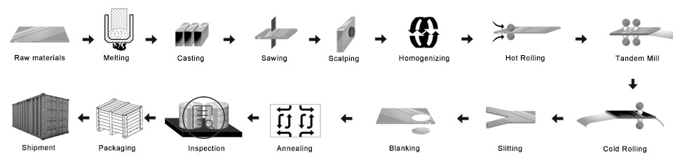
Aluminum Circles Process
Ingot/Master Alloys — Melting Furnace – Holding Furnace — D.C. Caster — Slab —- Scalper — Hot Rolling Mill – Cold Rolling Mill – Punching – Annealing Furnace — Final Inspection – Packing — Delivery
- Prepare the master alloys
- Melting furnace: put the alloys into the melting furnace
- D.C.cast aluminum ingot: To make the mother ingot
- Mill the aluminum ingot: to make the surface and side smooth
- Heating furnace
- Hot rolling mill: made the mother coil
- Colding rolling mill: the mother coil was rolled as the thickness you want to buy
- Punching process: become the size what you want
- Annealing furnace: change the temper
- Final inspection
- Packing: wooden case or wooden pallet
- Delivery
Quality Control
Assurance Below inspection will be done in the production.
- a. ray detection—RT;
- b. ultrasonic testing—UT;
- c. Magnetic Particle Testing-MT;
- d. penetration testing-PT;
- e. eddy current flaw detection-ET
1) Be free from Oil Stain, Dent, Inclusion, Scratches, Stain, Oxide Discoloration, Breaks, Corrosion, Roll Marks, Dirt Streaks, and other defects which will interfere with use.
2) Surface without black line, clean-cut, periodic stain, roller printing defects, such as other gko internal Control standards.
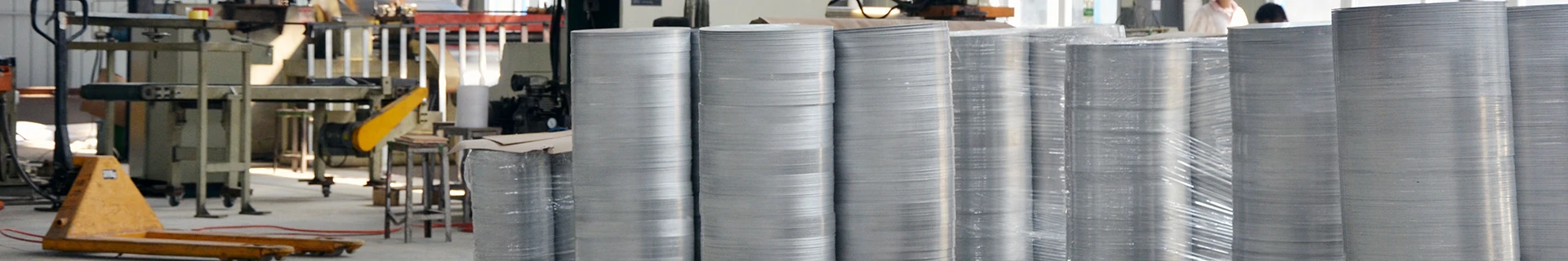
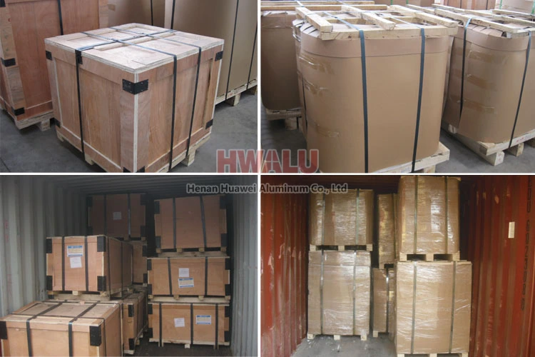
Aluminum discs packing:
Aluminum circles can be packed by export standards, covering with brown paper and plastic film. Finally, the Aluminium Round is fixed on a wooden pallet/wooden case.
- Put the driers side the aluminum circle, keep the products dry and clean.
- Use clean plastic paper, pack the aluminium circle, keep good sealing.
- Use the snakeskin paper, pack the surface of the plastic paper, keep good sealing.
- Next, there are two ways of packaging: One way is wooden pallet packaging, using the crusty paper packing the surface; Another way is wooden case packaging, using the wooden case packing the surface.
- Finally, lay the steel belt on the wooden box’s surface, keeping the wooden box fastness and secure.
Aluminum circle of Henan Huawei Aluminum. meet the export standard. Plastic film and brown paper can be covered at customers’ needs. What’s more, a wooden case or wooden pallet is adopted to protect products from damage during delivery. There are two kinds of packaging, which are eye to wall or eye to the sky. Customers can choose either of them for their convenience. Generally speaking, there are 2 tons in one package, and loading 18-22 tons in 1×20′ container, and 20-24 tons in 1×40′ container.
Why choose us?
In order to move with the times, HWALU keeps introducing the state of the art equipment and technique to improve its competitiveness. Always adhere to the business philosophy of quality as the center and customer first, to provide the highest quality aluminum disc circle series products to all parts of the world. More …